If you have to ask what is a NAS, then you pretty much don’t need a NAS. Basically, a NAS (Network Attached Storage) is the same as typical Personal Computer: CPU, motherboard, ram, hard drive in a computer case that attaches to your home network or work network.
The intro…
Yes, a NAS primary use is for storing your data. It is simply just a glorified USB thumb drive in a nutshell
This post is about my experience building my custom NAS.
There are multiple reasons that make me build a custom NAS:
- The Micro ATX case I am using doesn’t have enough space for a 3.5″ hard drive
- I want to access the same file across work computer and entertainment computer, and sometime windows tablet
- I don’t want to create a user account on my windows PC just to share some files temporary, as this user account will pop up in login screen.
- I don’t want to type my login for my PC into some body else PC just to access windows share while being at my homelab
- If I use windows file sharing and use my PC to share files, I have to turn on my PC like 24/7, yeah? Then how is it different than a NAS?
- Isn’t it better to run a dedicated NAS than the janky windows sharing which hard to manage what to share and what is the priviledges of those who can access the share? Do I have to install windows server to get better control of this?
- I want to automate the data backup process, which I haven’t done it yet until now
- I want to stay away from microsoft and their bullsh~t: bitlocker, M$ account, M$ cloud backup
- Commercial NAS still is a bit pricey and mostly with ARM chip to cut cost and also cut down power consumption
You might say, why don’t I use cloud base to store data and backup data? Well, I say f*ck microsoft and its onedrive, and I don’t trust google, more info here. I rather rent a hosting or a VPS and use it as my file server instead. But why would I?
Why would I choose 100Mbit internet speed over 1.0 Gbit local network, not to mention internet upload is only about 16Mbit for 100Mbit line. I can also go overboard with 10GBit network for a NAS if I want to!
I did rent AWS for a while to run my file server and also my old blog (ceezblog.info), but the cost ate quite a chunk of my budget so I retired that old domain after about 10 years. I thought I gave up blogging for good, but still here I am.
So yeah, building a custom NAS is pretty much the same as building a custom PC, just simple as that. Except it took me a few months from planning, buying stuffs to finishing the NAS. You know, buying stuffs from aliexpress is pretty much like lottery. If you’re lucky, you get delivery after 10 days. If not, it is 2 months or longer.
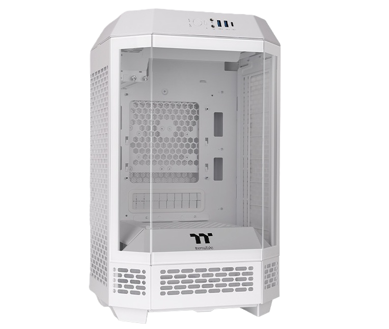
Choosing a suitable case for NAS
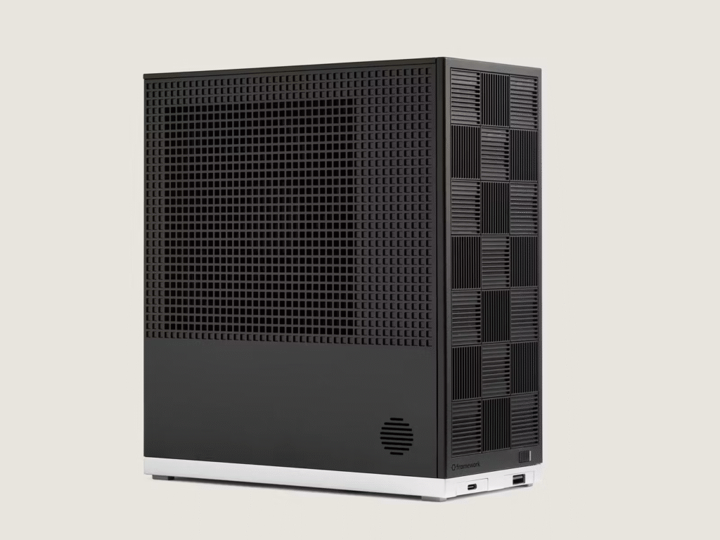
Some just uses ATX PC case, other picks HTPC (home theater PC) case, but the best is to use the case designed for quick-remove hard drive bay that designed for NAS.
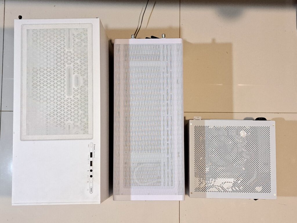
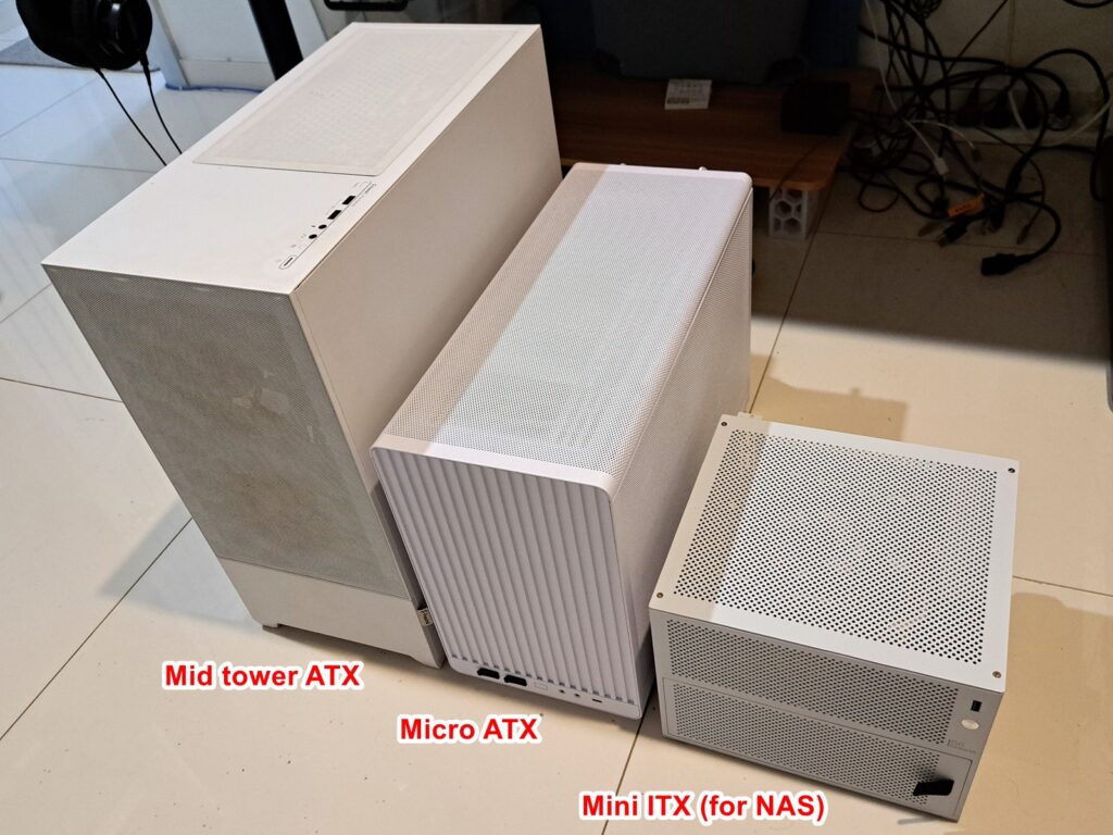
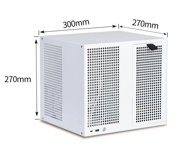
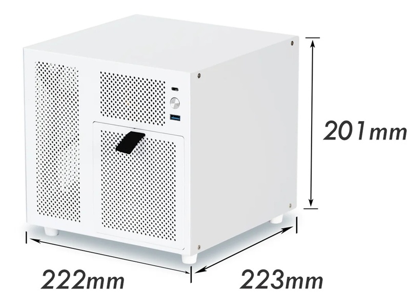
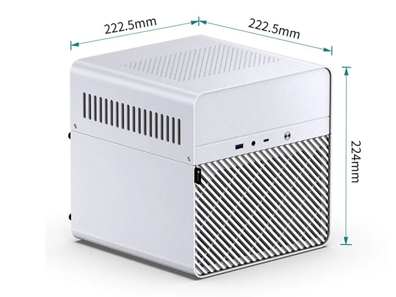
Below is visual comparision of different computer case sizes that I am currently using:
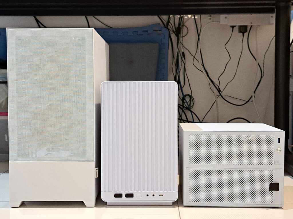
You can buy a gaming PC case a lot easier than for NAS. It is understandable. It’s like 100 persons buy computer, where as 95 is for gaming, 5 is for office use, and virtually zero is for NAS. Yes, I just make up the number. But I can see the market of custom NAS case is quite small.
The only place I can find NAS cases is amazon or aliexpress. Pretty much all of those NAS cases are made in china anyhow.
My aim is to reuse 4x 3.5″ hard drives I have for the NAS. There is no point to build the NAS but buy new hard drives along the way. So, 4-6 bays for 3.5″ hard drive it is. There are a few choices with theirs dimensions:
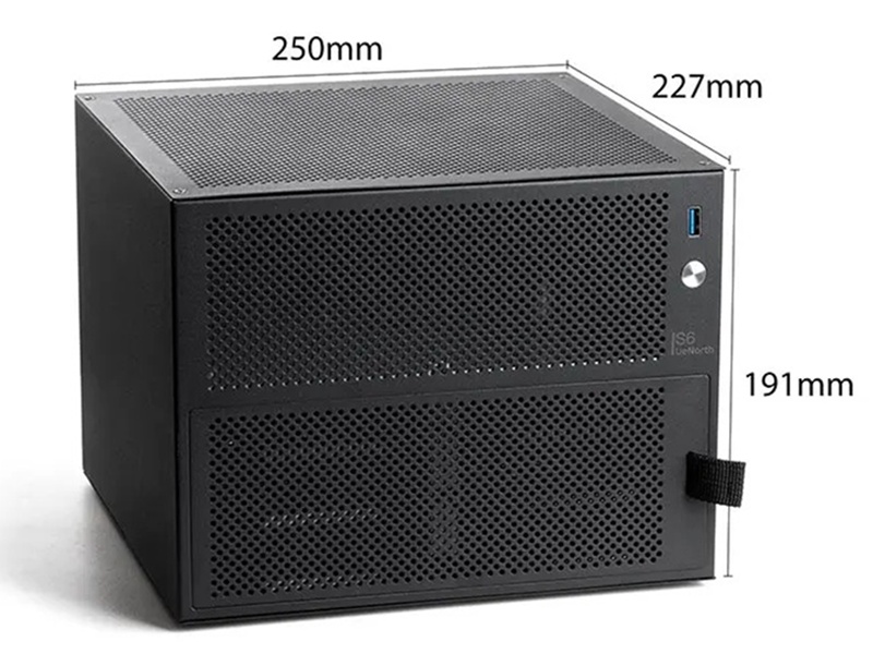
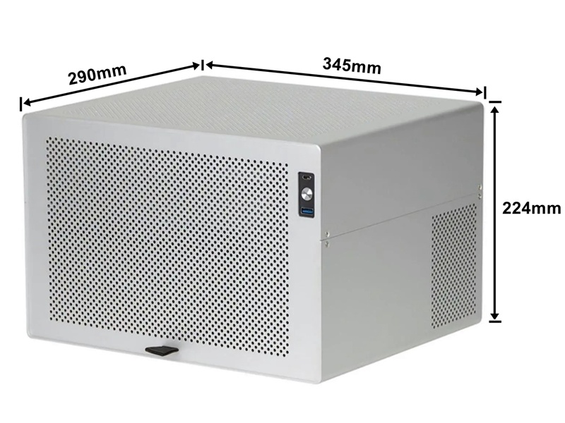
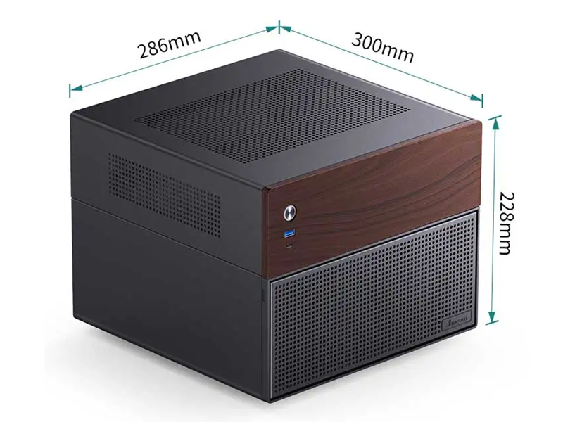
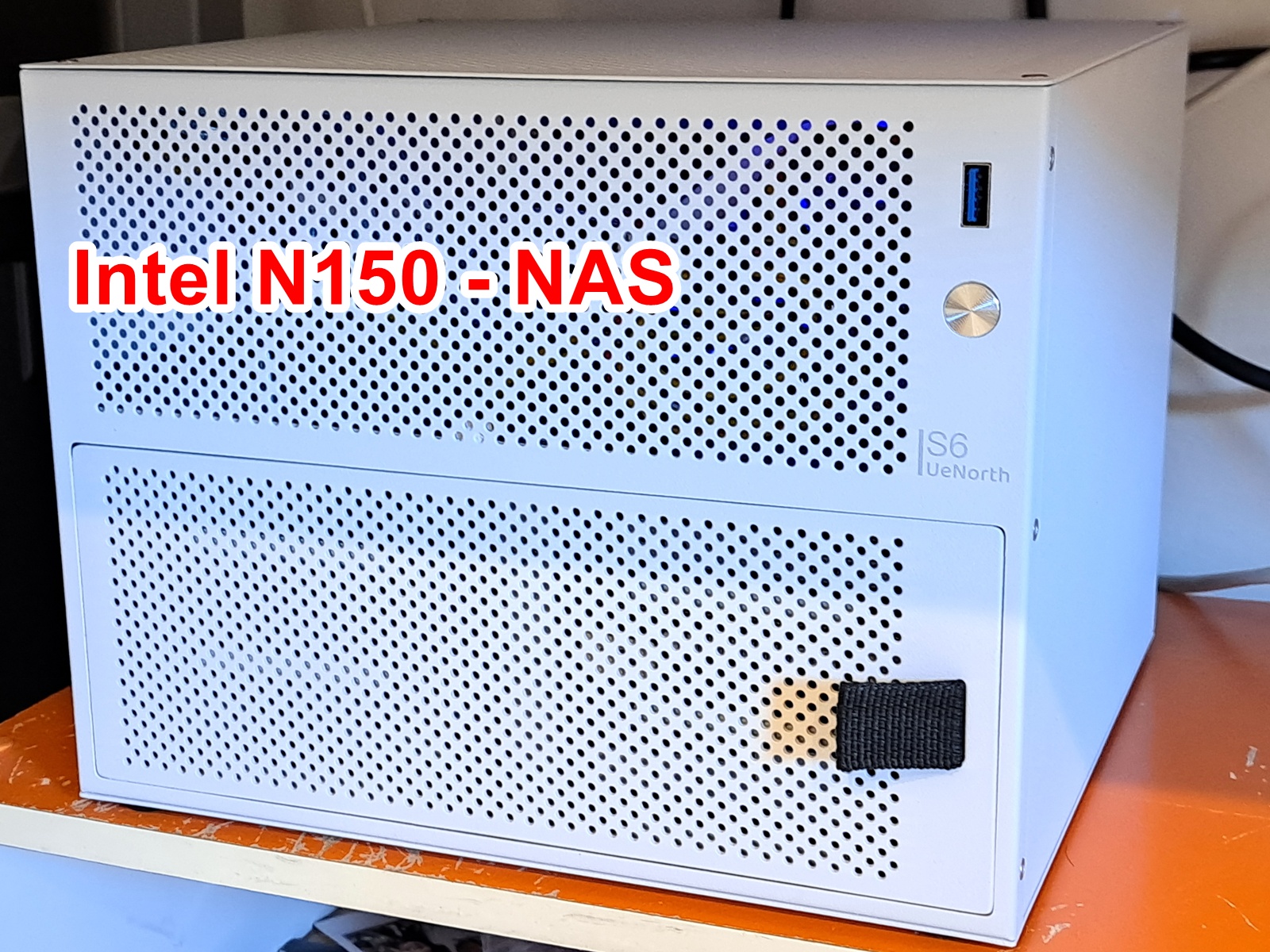
I decided to lock on UeNorth S6 NAS case instead of JONSBO ones. It is small enough and can hold 6 sata bays. I wonder if it is the same manufacturer of those constellation NAS cases (Aries, Sagittarius, Ursa minor), you know, North like in North star. I can see the design language of those cases are very much similar, like, the same power button, the same fabric tab to pull cover of the drive bays.
FIY, the NAS case is categorized as OVERSIZED SHIPPING, and it is extremely slow. It was over a month to get here in Australia.
Choosing the hardware: CPU and motherboard and PSU
I tried to design my own NAS case before, but failed. Actually, design a mini ITX case is not hard, as everything has dimensions, screw hole locations and all. The hard part is to design the removable caddy for 3.5″ hard drive. I already bought the parts for that but decided to give up. I don’t want to buy caddy for DELL server or HP server. My target is not really a budget NAS, but more like to build something nobody’s done before, something like almost impossible, such as use 2.5″ laptop HDD box to run 3.5″ HDD, say, a fun challenge for myself.
I originally had 2 plans:
- USB HDD box + Mini PC (HP elitedesk) + 30A 12V PSU
- ITX board (intel N150) + sata cable + old ATX PSU
Those HDD boxes are for 2.5″ laptop HDD that lacks of 12V power, but I soldered extra wire for 12V DC to be able to use with 3.5″ HDD and it ran just fine. FIY, 12v rail for the motor to spin the plates, while 5v rail is for logic board of hard drive. And yes, without 12v power, 3.5″ hard drive just won’t work.
My plan was to pull the pcb of those HDD boxes and solder extra wire to run with 12v 30A PSU. This to provide the missing 12v of those laptop hdd boxes
Some guy reported the mini PC can actually run off 12v instead of 19.5v. Afterall, the voltage will be dropped down to, say, 1.25v for the CPU or RAM, or 3.3v for NVMe drive… The only thing I can think of that could use 12v or +/-12v is the amp for headphone output. But still headphone amp still can be done with capacitor output and run on single 5v rail. Really, the buck regulator will drop down to target voltage regardless of input voltage of 19.5v or 12v.
The idea of attaching USB hard drives to a mini PC does have legs. Basically it is DAS + mini PC = NAS, where DAS is direct attached storage. I still have a bit of concern about 5v USB to power logic board of the hard drive. You know, USB is not the most reliable thing, we sometime have to unplug the USB to make it work again. I guess this is due to the 5v USB has to go through tracks and traces on the PCB and/or through mosfets on the motherboard, it is certainly not as reliable as 5v directly from the molex connector. So that I also had plan to have buck converters to have dedicated 5v rail feed to that usb box pcb.
After a few weeks sitting on it without any progress, I decided it’s best to use my time for something else, and I moved on with buying an Intel N150 ITX board from aliexpress.
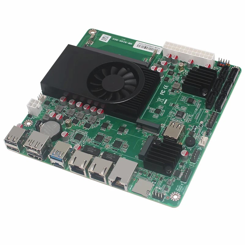
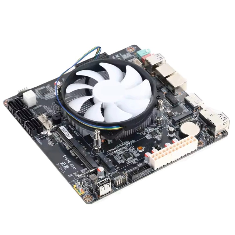
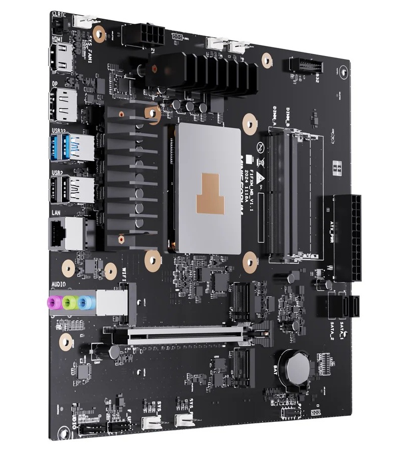
I was tempted to buy the board with 4x RJ45 port thinking I could build it as a NAS + router + managed switch. Doing more research, I find out that each RJ45 port ties to an intel NIC (network interface controller), which ultimately connects to the CPU via PCIe lane, probably. So, any routed traffic from 1 NIC to another is done in software, bummer!
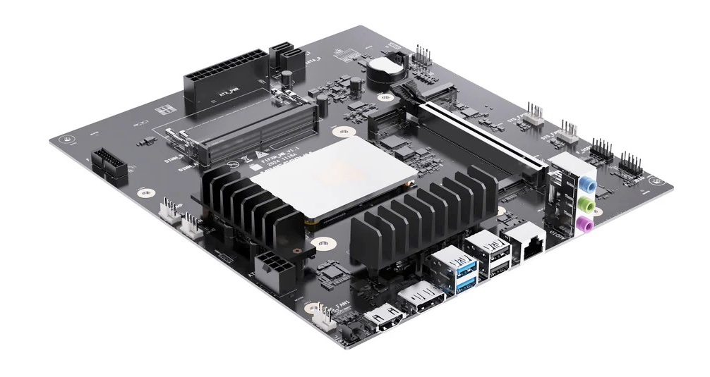
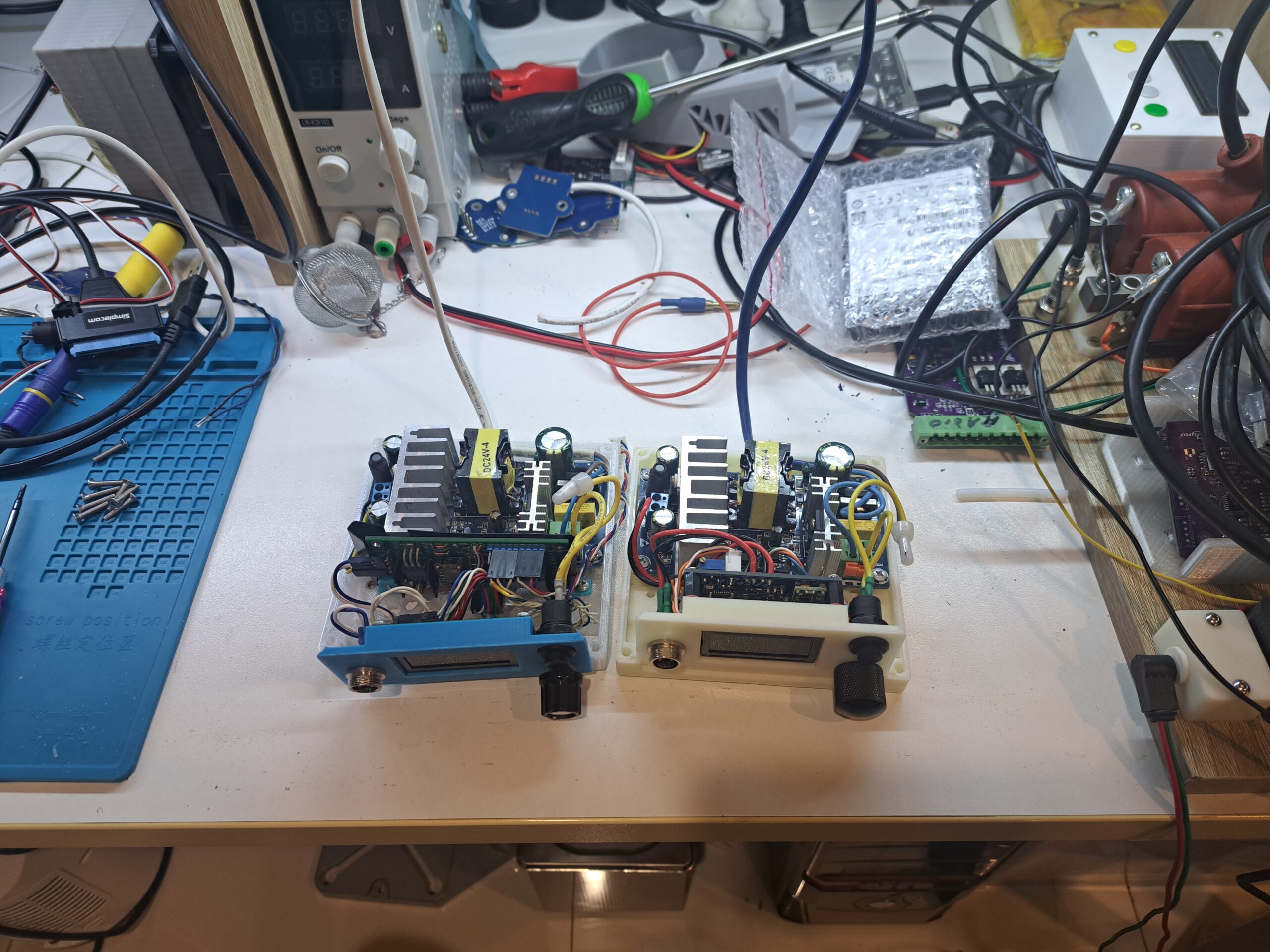
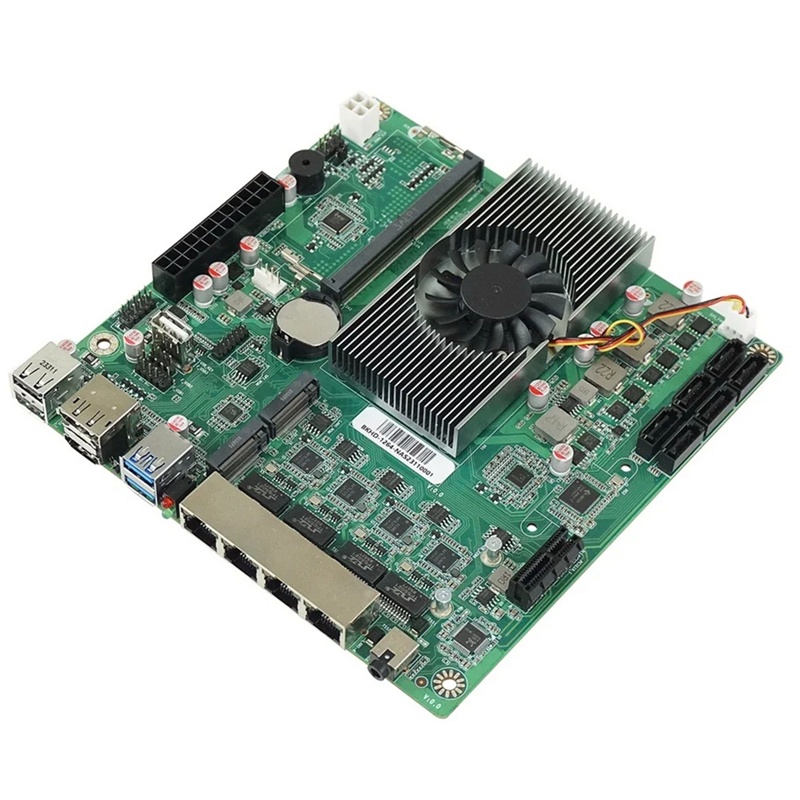
So I chose the cheapest option for N150 NAS motherboard: N150 NAS DDR4 Motherboard 6x SATA3.0 2x Intel I226 2.5G Mini ITX. It’s the one on the right. I went with DDR4 for availability because you can buy used SODIMM DRR4 easier than SODIMM DDR5. Ram rarely fails, a used DDR4 is still plenty good for my needs.
The use case for multi NIC computer like this is for multiple instances of virtual machine where each instance can have its own NIC and totally isolated, just like a completely different computer. I chose intel N150 for low power consumption, I don’t think I need to run any VM so I prefer a NAS with only 1 or 2 ethernet port but have plenty SATA ports for my hard drives. Additionally, my PC has only 1.0GBit NIC, and my switch is only 1.0GBit, there is no point having a 10GBit NIC for the NAS.The bottle neck is the HDD as it is about 120MB/s, the same speed of 1GBit ethernet. So I just pick the board on the right since I have some room for the board to fit inside the case.
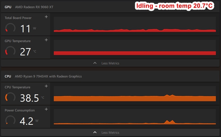
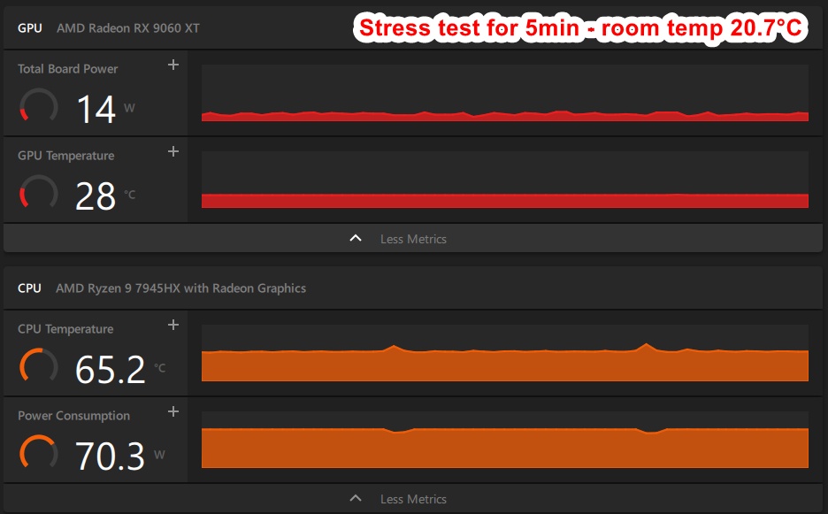
Running some power consumption tests yielded some interesting results:
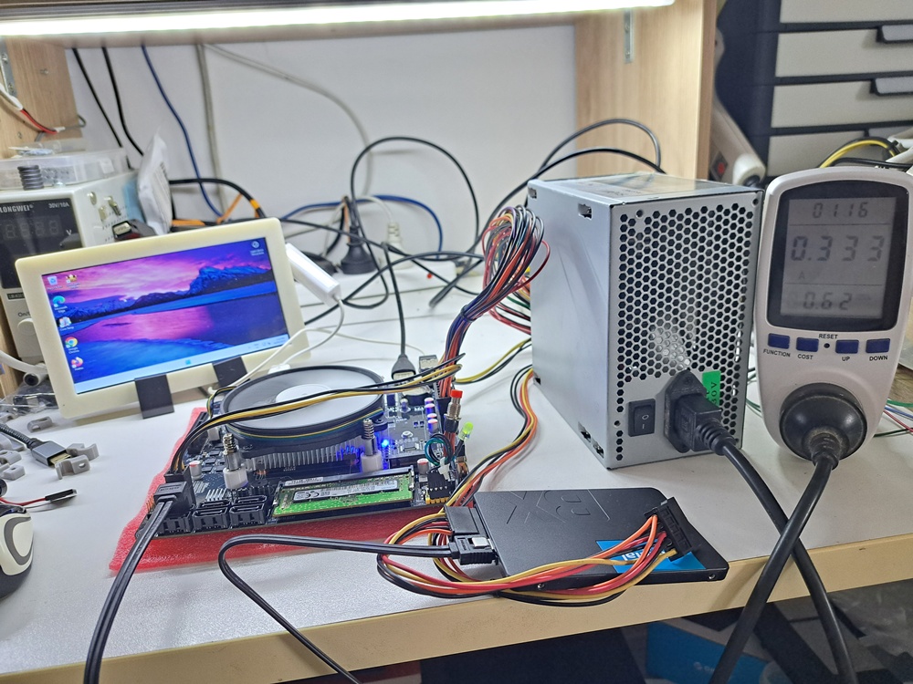
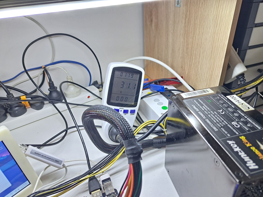
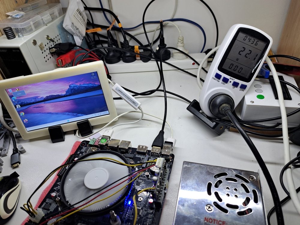
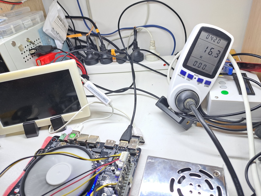
The test bench: 8GB ram + Sata SSD + USB 2.0 to RJ45 adaptor + 7″ LCD powering from USB port + running windows 11.
While the setup with ATX PSU pulled about 31w at idle and around 53w at full load, the setup with 12V-20A switch mode PSU + Pico ATX PSU only took 22w at idle and 42w at full load. When I unplugged the USB power for the mini LCD, power consumption fell down to 16w. The math is about 70% efficiency (= 22w / 31w * 100%) for ATX PSU if we considering 12v-20A psu setup was 100% efficiency. So the actual efficiency is lower, about 50-60%.
To be fair, ATX PSUs are designed to be highest efficiency when it is around 50-80% of max load and 31w is only about 6% load of 500w PSU. That is why the efficiency is terrible at light load.
For the test system above, a 150w PSU is good enough. But, there are 6 sata bays for 6 hdds, each hdd can take extra 18w, make it around 108w. The maximum power consumption of this NAS would be around 170w. To be safe, The PSU for this NAS should be 250w or higher.
Rule of thumb when choosing power supply for electronics: choose the power supply that can do at least 30% more of maximum load of the system. It’s just that the higher wattage, the pricier they get.
I bought 350w flex PSU for this NAS. It costed me only AU$45 shipped from aliexpress.
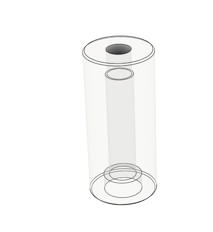
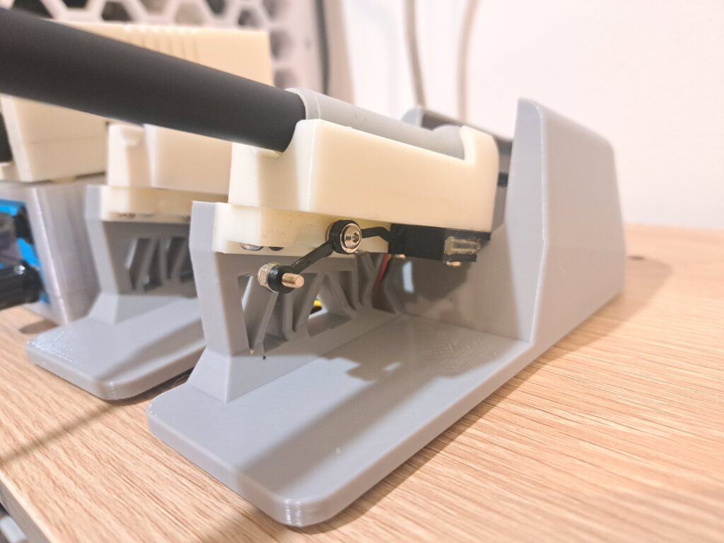
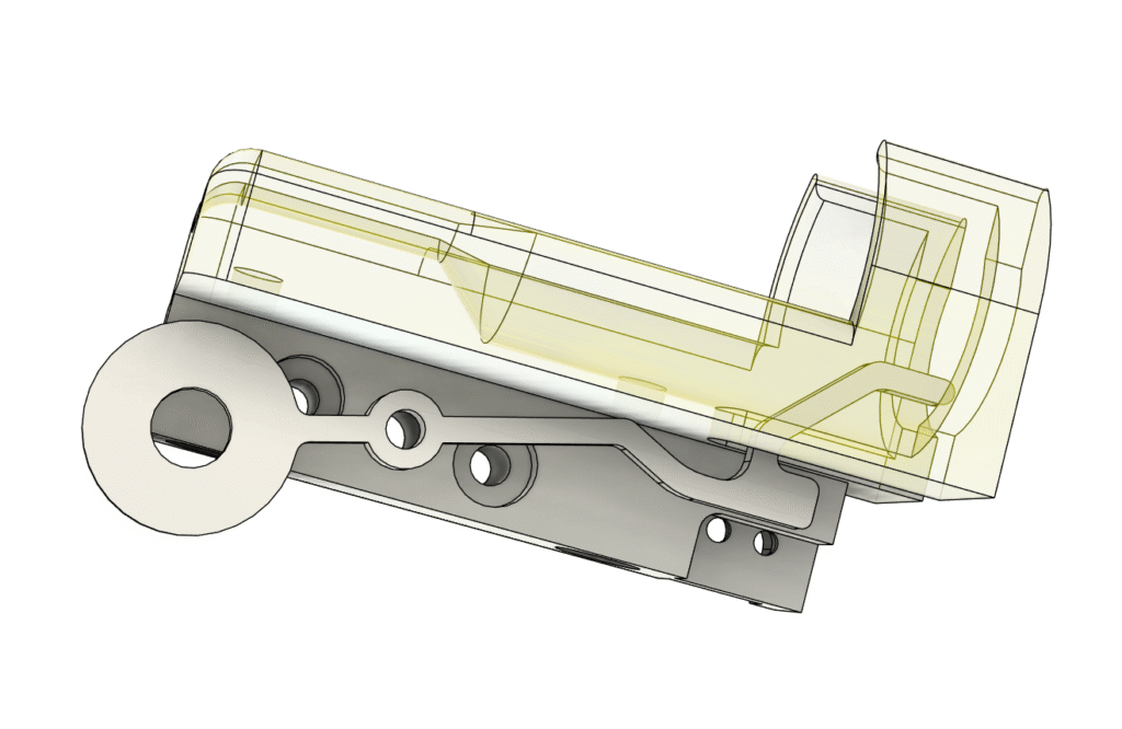
Of course, the cheap flex PSU doesn’t have fan speed controller to limit the noise of those crazy high speed 4020 fans. Those fans can spin very fast 5000rpm to 18000rpm. This high speed fan generates irritating high pitch noise, that I have to print a fan shroud to eliminate that noise
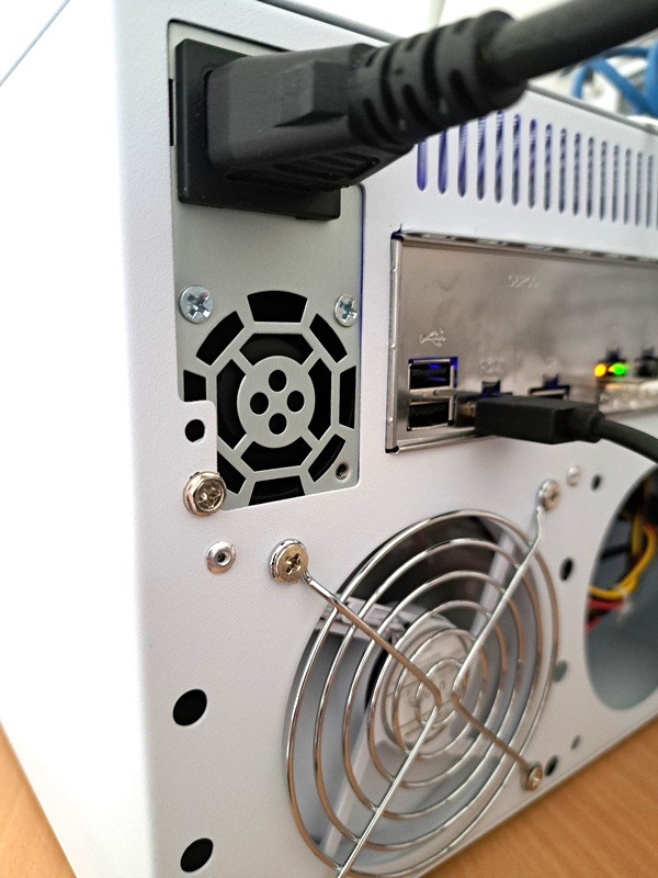
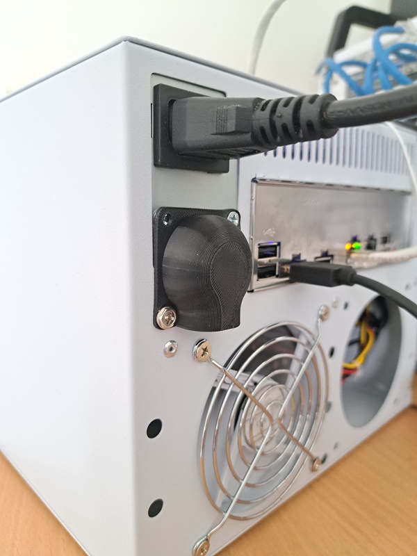
Get the shroud for 4020 fan here
Assembly the NAS
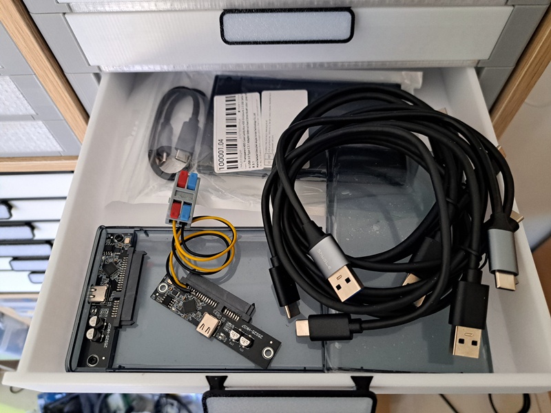
The case came without any fan. It was expected, so I bought 3x 9015 fan for it.
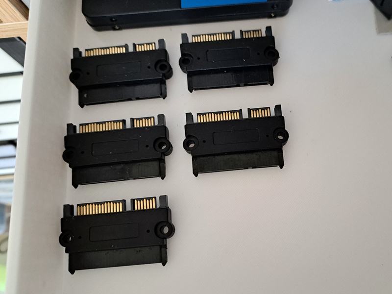
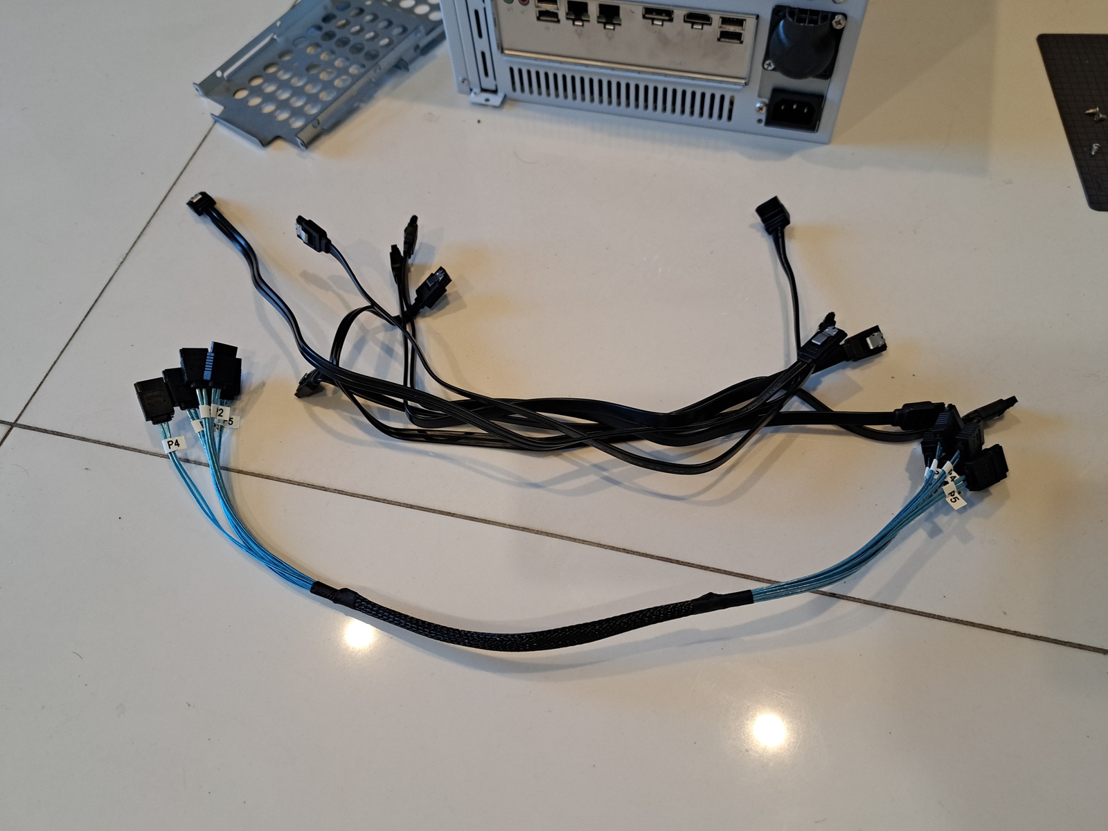
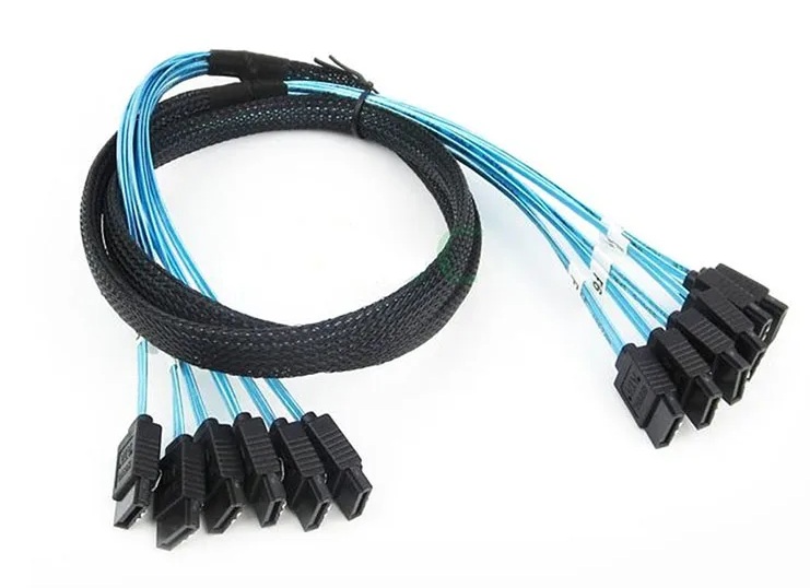
I also bought about 10x sata cable. Turn out those normal sata cables are too stiff to use in this tiny case. So that I had to buy sata cable bundle. Before I build this NAS, I didn’t know there is such a cable bundle like this.
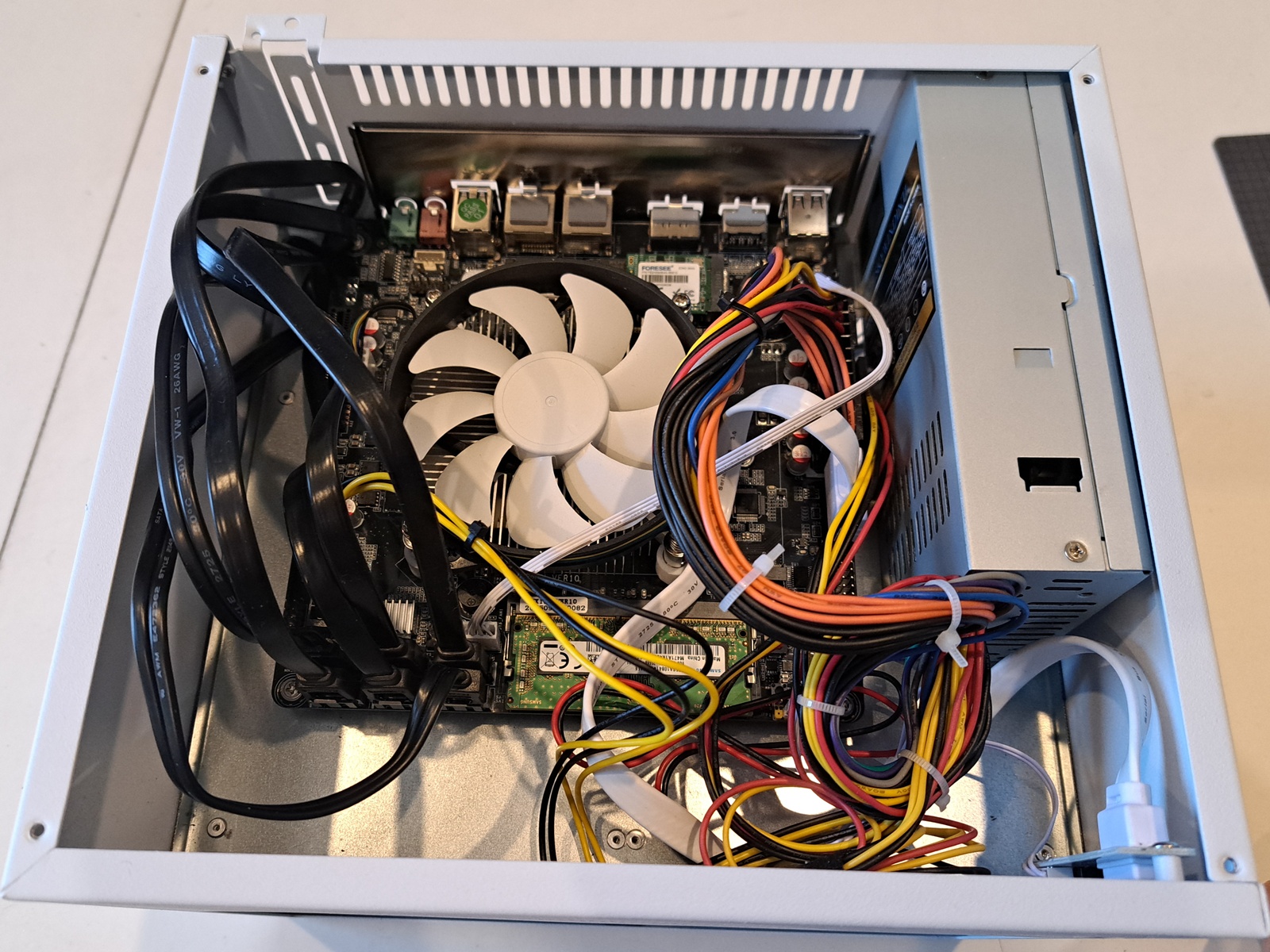
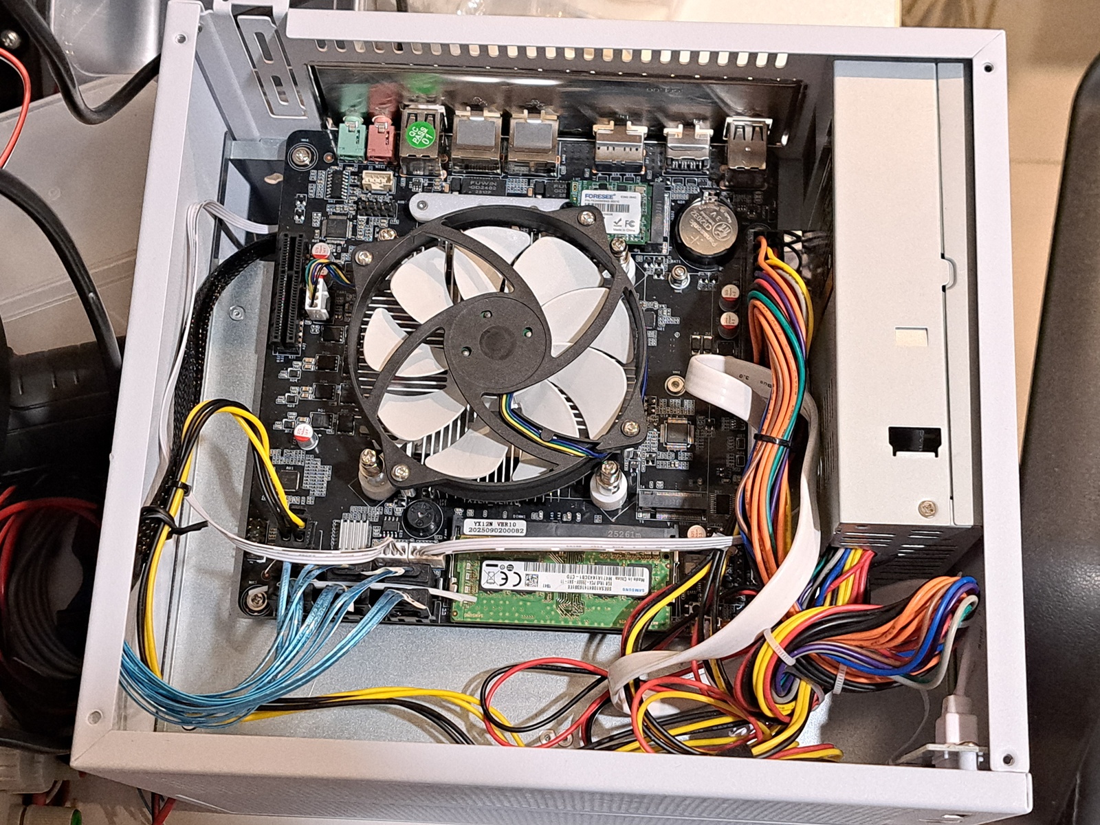
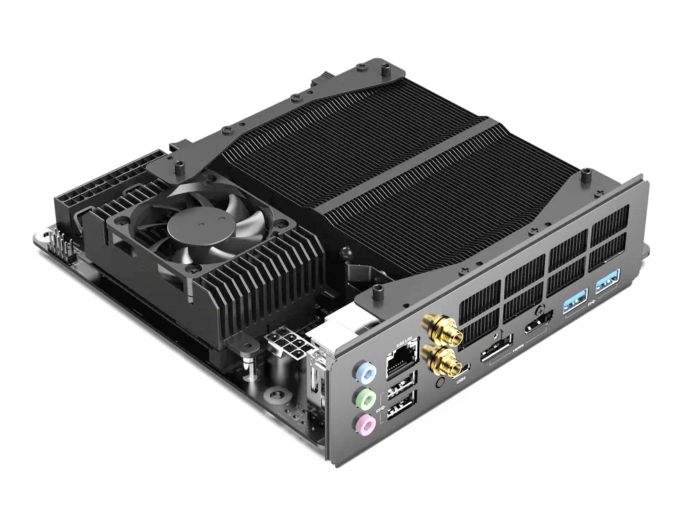
The intel N150 max TDP is 15w, it can be entirely cooled by passive heatsink. But since there is no exhaust fan in the upper half of the case, hot air will just be trapped and circulated around the CPU fan instead of going out of the case. After consideration, I flip the CPU fan from blowing down the CPU to blowing upward. So that a little bit of hot air will be forced to go through vent holes on the top panel and thus fresh air will get in through the front. I could design duct at the CPU fan to get more air come out easier, but meh.
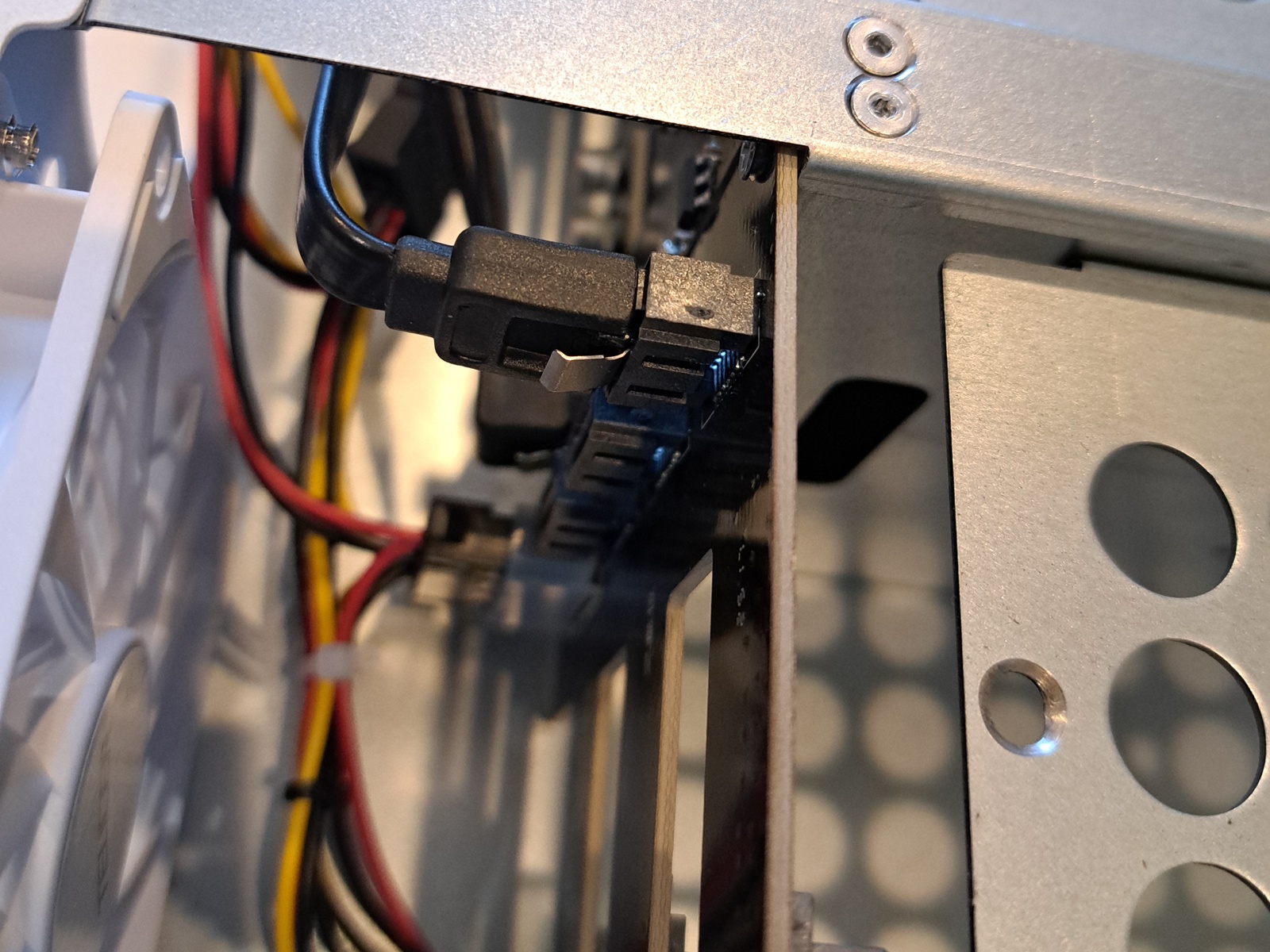
The case is laser-cut so that the edges are very sharp. It is understandable with low volume product to be laser-cut rather than made with punching or stamping machine. I had to run sand paper over all edges of the steel hdd trays. It just is too sharp, almost like razor sharp. It cut me when I tried to plug in those sata connectors at the backplane pcb.
The process of assembly everything together is quite straight forward:
- Install the motherboard
- Install the PSU
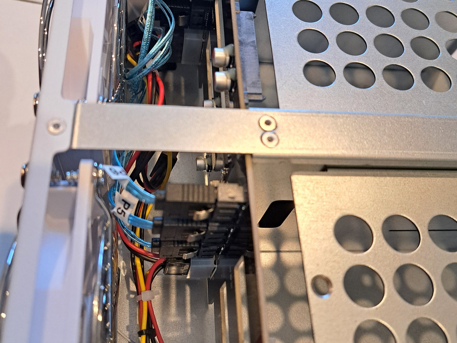
- Run power wires to the bottom half
- Run sata cables to the backplanes
- Cable management
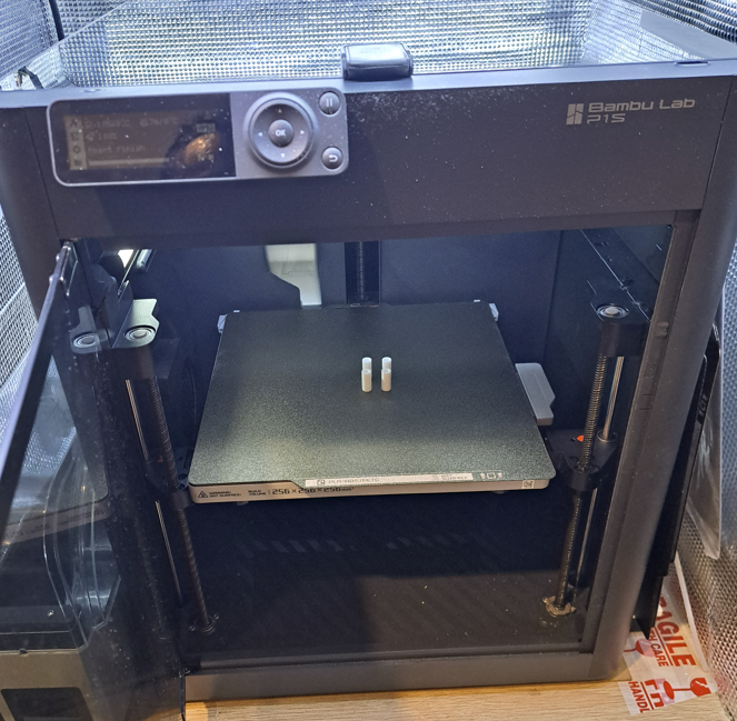
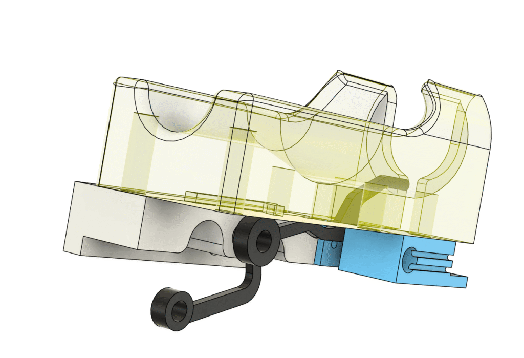
I have a 64GB NVMe 2230 that I want to use. This drive was from a steam deck. It’s quite useless for everything else except it’s perfect to use as boot drive for the NAS. I just have to design a bracket for 2230 to sit in 2280 and 2242 slot.
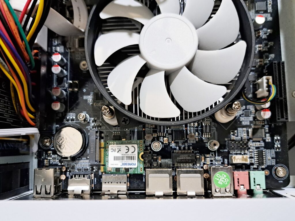
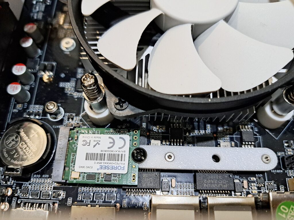
If you have the same problem, you can download the 2230 bracket here
Here comes the troubles : the software for NAS
My needs from the NAS is pretty simple:
- Backup my work data regularly
- Only backup if there is any change to the data
- File server to store movies
My works are almost about firmware for microcontrollers. And the firmware rarely changed, unlike PC software that needs constant bug fixes. Once the firmware is at working state there won’t be much change. It could be only one minor change after 2 years or so. So that, backup everyday is just a waste and make it a lot harder to trace back where was the change was made when going through tons of archives, like 365 archives a year if I backup everyday.
Of course, once in a while I should copy the archives into a USB drive and keep it offsite for extreme measure.
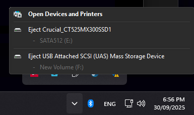
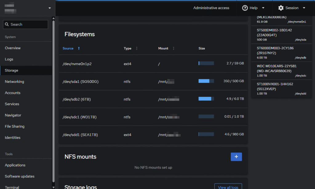
My first try was trueNAS. It is generally very good, the web sysadmin to help you to control every aspect of the NAS is very straight forward and intuitive. But it requires to format the hard drives into ZFS. I have no problem with formating 1TB drives, but I also have 6TB drive that 70% full of movies that I don’t have any mean to dump those data to in order to format this drive into ZFS. Yes, it was currently NTFS.
While experimental with trueNAS, I discovered cockpit. Which is exactly what I need. I don’t want to fiddle with command line for everything, too much to learn, so a web sysadmin interface is like a godsend for me.
So I decide to have linux + cockpit + cockpit file sharing as my base software for the NAS.
Then I tried debian 13, Ubuntu server 24.04.3 LTS. I also tried some desktop flavour like EndevourOS and KDE neon for this NAS. I know, I know, it is suppose to be a headless server, why would I want a distro with desktop environment? Debian 13 inet installer does have an interesting flavor: freedombox to be installed along. It’s like the desktop environment but on the webpage for the headless server, neat!
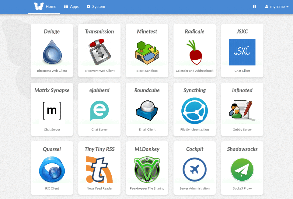
Freedombox interface
Heck, I even tried to install Arch, but the installer just boot into bash shell. There was no GUI, no instruction. I was lazy and gave up on Arch
When testing freedombox, I tried install cockpit and config samba there but no joy, windows 11 couldn’t see samba share whatsoever. I spent a week trying debian 13 and ubuntu 24 with cockpit, you know, following instruction to install from the website but still there is no sign of life from windows 11. So, I had to get my hand dirty and dig deeper. I had to use a port scan tool, which I collected since 2012 and it was flagged by Windows Antivirus immediately the moment I unrar the file. Well, I’ve been using this tool for years, long before windows 10 without problem. Then I realized that port 139 and port 445 was not accessible from windows 11 machine. And sure enough, samba wasn’t installed along with cockpit file sharing even though samba was listed as dependency, as it should install all dependencies along with main package right? Then install samba for real this time and also install wsdd (web service discovery host daemon) just to place nice with windows. Windows 11 does work with samba now.
Then I go ahead and install cockpit identities, cockpit navigator. But some how I broke cockpit while manually compile and install those. Do more reading, I realized one of those plugin only supports up to ubuntu 20!
Up to this point, I already got my hand dirty and dip deep into linux command line world, like recompile those packages from source to install them, mostly still follow instruction though. I couldn’t fix the cockpit I broke, so I decide to install debian 12 and start fresh. Now everything works the way it should be.
Lesson learned: do not install the newest version of linux for server, as too many packages are changed and it could break the software you want to use. Stay one or two version behind the newest one for a server. Say, debian 13 is newest at this time of this post, just use debian 12 instead. You have to give those software a few years to catch up with newest release of the OS. You know, linux world is mostly free, most of them are doing this at their spare time. Unlike microsh!t, its programmers get paid fulltime just to break the old trusty windows we used to use.
On some side note: I did run KDE neon on a hp elitedesk mini pc a while ago until I gave that mini pc away as a part of firmware flashing machine. Yeah, instead of spending time, a lot of time to setup the flashing environment on customer PC, I just gave him the mini PC and that’s that, quick and easy.
So this is the list:
- Debian 12
- Cockpit
- Cockpit identities
- Cockpit Navigator
- Cockpit file Sharing
- Samba
- Wsdd
- Transmission
And my NAS just accept NTFS without any complaints, unlike trueNAS which requires to format the drives into ZFS.
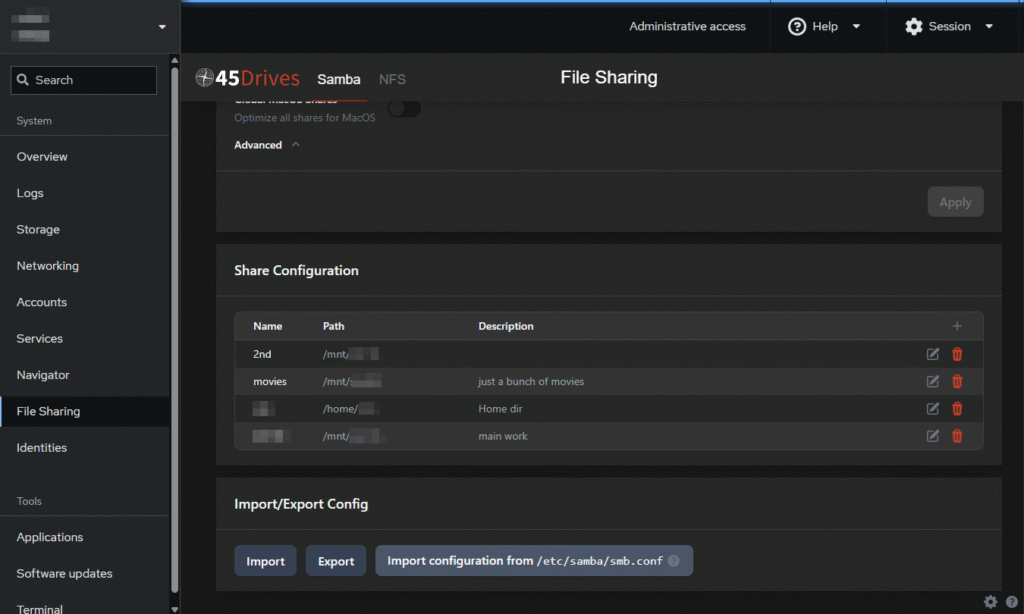
When I insert a new hard drive, I just have to mount it and assign a share to the location I mount. I can easily add new share for guest, a lot easier than mucking around with “sudo nano /etc/samba/smb.conf”
Backup script to backup data
As mentioned before, I need to backup data regularly but only backup if changed. So I wrote a shell script to do this job
#!/bin/bash
# This script will backup a <source folder> to <sync folder>, checking for changes of subfolders
# If there are any, it will zip each modified subfolder into a separated timestamped archive
# Dependencies: p7zip, p7zip-full, rsync, pv (pipe viewer)


#Location of Source folder
source_folder=/mnt/sdb/WORK_DATA/

#Location of Destination folder that you want to backup to (existing extra file could be deleted)
sync_folder=/mnt/sdc/SYNC/WORK_DATA/

#Location of zip archives if there is any changes between synced folder and main folder
archive_folder=/mnt/sdc/ARCHIVE/WORK_DATA/

#Log file
log=${sync_folder}../../backup.log

current_dir=$PWD
echo -e "\n\n"
echo "-----------------------------------------------------------------------------------------"
echo "   This script will backup folder WORK_DATA from SEA1TB hard drive to WD1TB hard drive   "
echo "-----------------------------------------------------------------------------------------"
echo -e ""

mkdir -p ${sync_folder}
mkdir -p ${archive_folder}

echo -e "--------------------------------------------\n$(date +'%Y.%m.%d %H:%M')\nStart Backup ${source_folder}\n" >> $log
echo -e "Destination: \n     ${sync_folder}\n     ${archive_folder}\n" >> $log
#Move to [source folder] to get a list of subdirs to sync_list.txt
cd $source_folder
find . -mindepth 1 -maxdepth 1 -type d -exec basename {} \; >${current_dir}/sync_list.txt

#Move back to current folder
cd $current_dir

#Loop through all subdir of [source folder]
 while read subdir; do

	#Create folders again just to make sure
	mkdir -p ${sync_folder}$subdir
	mkdir -p ${archive_folder}$subdir

	#echo "checking for different between source and sync"
	diff --brief ${source_folder}$subdir ${sync_folder}$subdir > /dev/null
	if [ $? -eq 1 ]; then
		echo  -e "- Item $subdir has been modified since last sync"

		#syncing
		rsync -avh --ignore-existing --checksum --delete ${source_folder}$subdir ${sync_folder} | pv -F "     Syncing...  %t" > /dev/null

		#zipping
		7z a -t7z ${archive_folder}${subdir}/$(date +"%Y.%m.%d_%H-%M").7z ${sync_folder}$subdir | pv -F "     Zipping...  %t" > /dev/null

		#logging
		echo  -e "- $subdir changed -> synced + zipped" >> $log
	else
		echo  -e "- Item $subdir in synced drive is the same"
		echo  -e "- $subdir not changed -> not synced" >> $log
	fi
done < sync_list.txt

rm ${current_dir}/sync_list.txt
echo -e "\n\n" >> $log
echo -e "\nJob done!\n"
So, my main data is in /mnt/sdb/WORK_DATA/ and a complete identical mirror is at /mnt/sdc/SYNC/WORK_DATA/ on a different drive as a backup. I also have archives stored in a third location /mnt/sdc/ARCHIVE/WORK_DATA/ which has zipped files. The script won’t zip the whole WORK_DATA folder, but zip each individual subdir into a zip file only if there is any change in that subdir when the script runs.
Let say, I have
- /mnt/sdb/WORK_DATA/kicad_project/ to store all PCBs I ever work on
- /mnt/sdb/WORK_DATA/stm32_project/ to store all firmwares stm32 micros
- /mnt/sdb/WORK_DATA/esp32_project/ to store all firmwares stm32 micros
- and so on…
So in ARCHIVE folder I’ll have
- ./WORK_DATA/kicad_project/
- 2025.11.10_07-54.7z
- 2025.11.11_09-20.7z
- ./WORK_DATA/stm32_project/
- 2025.11.10_07-54.7z
- ./WORK_DATA/esp32_project/
- 2025.11.10_07-54.7z
kicad_project archive folder has one extra file, because I only made changes in this folder between 2025.11.10 07:54 and 2025.11.11 09:20 while others folders are the same as before.
This is very much the same as CCTV camera only records when there is movement on the screeen.
Basically, I can put those 3 locations in separated drive to ensure highest chance of survival if one drive fails or acidental deletion or whatever. You know, nothing lasts forever, everything will fail eventually.
For now, I just put both mirrored data and zipped backups in the same drive, it doesn’t matter much. I do copy the archives to USB drive every now and then for extra safety.
Then next step was to setup cron job to run this script how frequently I want it to be. This is as easy as running crontab -e to edit the cron job config.
The total budget for this custom NAS
- intel N150 NAS motherboard — $205
- SODIMM DDR4 8GB — $25
- UeNorth S6 case — $108
- Flex PSU 350w — $44
- 6x Sata cable bundle — $12
- 3x 9015 fan — $17
- 64GB NVMe — free
- 4x 3.5″ hard drives (6TB, 2x 1TB, 500GB) — free
The total cost is AU$411, not as really in the budget that I thought it would be, but sure it isn’t bad compare to Synology NAS or alike. If I include the cost of the hard drives, it would rise up to about AU$800.
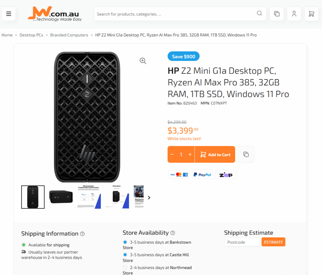
Compare to prebuilt NAS that has only about 1 or 2GB ram and run on dual core ARM CPU @1.7GHz, it’s pretty much in the ballpark of AU$400 to AU$600 to this one.
Certainly, this custom NAS cannot compare to those of one notch better, like MINISFORUM N5 AI NAS (AU$1700) or UGREEN NASync DXP6800 Pro (AU$1655). Those NAS have better CPUs for sure (intel i5 12th gen or Ryzen 7 255). Sure enough, those NAS will be a lot better in heavy tasks like plex transcoding 4k video. But for me N150 is well enough for my use and totally worth it. And it also doesn’t burn too much of electricity.