As long as I can remember, I’ve been being a windows user since for ever: Win95, Win98, Win2000, Win9x, WinMe… It’s kind of a part of my teenage: installed windows 98 for 3 times a week as it just broke after a day. I was a loyal windows user despite of bugs and all because there was no other option. But these recent years have me change my view about windows and Microsoft, or I should say Microslop.
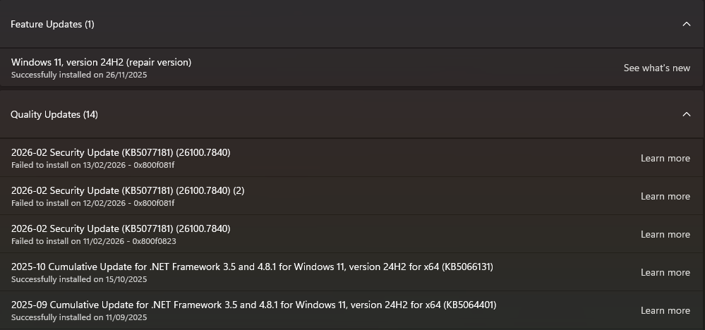
Well, I’ve been pausing windows update for a few months now, but this time, it didn’t let me pause windows update anymore.
Yep, there is an important update that won’t allow me to pause updates. That is KB5077181. This update reveals that my current windows is a ticking timebomb. More to it later.
I had a nice quiet time during the past few months without microslop secretly download the update and cause FPS drop during game sessions. The last update I allowed to get was about 3-4 months ago.
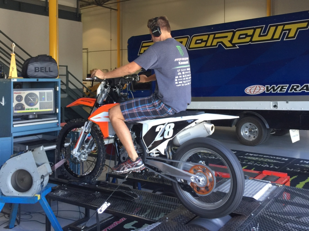
Do you see that I get update for .NET Framework 3.5 and 4.8 which is ancient according to Microslop standard. That is because I need those frameworks for the app SV Toolset that I am maintaining. The users of this app are mechanics who do dyno tuning for motorcyles. Of course, they are not tech-savvy. They probably don’t know how to invoke the pop-up menu. And often the PCs that used for those dyno machines are probably about 20 years old, as old as those dyno machines. Those PCs usually are not connected to the internet. No need to take the risk that Microslop update will break the app. And yes, .NET Framework 3.5 is already installed as a part of windows since win7, hence it is the framework that SV toolset is using.
The picure above was stolen from the internet just for describing the dyno machine.
And more than one case, the PCs run those dynos are on windows 7, just because the manufacture of that machine went out of bussiness 20 years ago! Matter of fact, I did a rescue of data and software of a dead PC (Pentium 4 core2quad) and transfer it successully to a hp elitedesk g3 and run on windows 11. Took me a solid few days to fiddling with mysql and all.
Yeah, my SV toolset has to run probably on those windows 7 and windows 10 machines. I have to make it backward compatible. It is already hard to write an app to communicate with BLE on windows 11. Apparently microslop makes it extra hard for me with recent update of visual studio community 2022 that I am using.
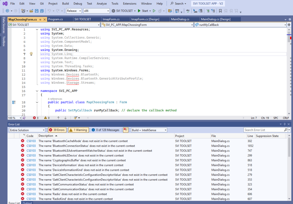
The newest update for VS this time removes support for windows 10, which only I know after I did the update. It also breaks the Windows namespace reference by delete the old windows ux (windows.winmd – 10.0.18362.0) for windows 10 that I am currently using for SV toolset.
I was panic for a second there. Then I checked the reference, it still there but somehow it couldn’t understand those reference of Bluetooth namespace.
Fortunately, I have a backup of those windows ux packages on the NAS. Then I just remove current Windows reference and add a different one. So, I go ahead and make a minor update for the app.
You might ask, what does it have to do with windows 11 as a ticking timebomb? Well, I went derail there. But it happens just the right time of this fricking KB5077181 update, just like the last straw.
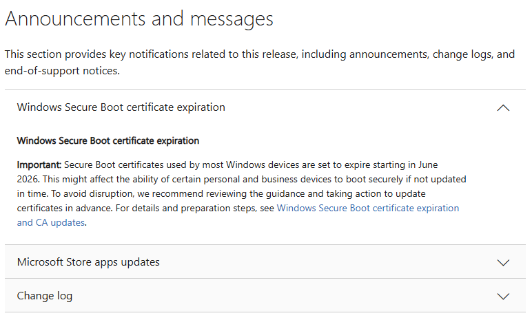
So what is this KB5077181. I took screenshot of the page
Secure Boot certificate of most Windows devices are set to expire in June 2026. In Layman’s terms, if your PC cannot get this fricking KB5077181 update, you cannot boot into windows after June 2026. And if your PC is bitlocker enabled (by default) and you don’t have the key (or backup the key before hand), then you will be probably completely f*cked. You cannot take the hard drive out and copy your data because it is encrypted by bitlocker (file/folder name still looks good but data in all the files are encrypted by bitlocker). It is the frigging same of ransomware that encrypts your data and holds it hostage.
The thing is, Microslop automatic backup the bitlocker key to your Microslop account without your knowledge or consent. And if somehow, microslop doesn’t have that key, just like my case which I never log into microslop account for my current PC, then again, you are f*cked. Basically, any change to the secure boot (key reset, faulty tpm chip, whatever…) Windows won’t boot and the hard drive now just contains some garbage data that you cannot use anymore.
Yeah, I can see some scenarios where top security CIA spy stuffs would need the bitlocker to prevent the enemy reading the data. But for mundane people like me, bitlocker is just jackshit.
Fortunately for me, I have built a NAS and now I my work data stored directly on the NAS, nothing important stored locally on my PC.
Of course I still have to reinstall and reconfig the software I use, such as visual studio, STM32CUBEIDE… in the case of catastrophes such as windows 11 Secure Boot certificate gone. But when that time ever happens, I am ready to go back to Tiny10 just because I have to run frigging F*ck-U-sion (or once it’s called fusion360), otherwise it would be fedora or linuxmint.
I might go on ape mode and delete the current windows if the windows update keeps being annoying to me again and again.
I wish to go back in time when win32 app didn’t have to be whitelist by microshit and when AI sh*t was just a product of hollywood. Happy those days…
Nowadays, too many companies get away with enshitification by just using the magic shield “for security”, like those frigging companies that goes full throttle against right to repair movement. Let’s show ’em what we can do with our wallet.
-Hey Microshit, you won’t get another dime from me. I paid for microsoft partner account with foolish thinking publish on M$ store would whitelist my app. I paid for windows 10. I don’t need windows 11, 12 or 13. I don’t need Cortana. I don’t need copilot. Let me be with windows 10.
I am changing my habit of using some small tools like notepad and paint to notepad++ and Greenfish Icon Editor. It’s been a good journey but you have turned the journey very painful for me.
If you have to ask what is a NAS, then you pretty much don’t need a NAS. Basically, a NAS (Network Attached Storage) is the same as typical Personal Computer: CPU, motherboard, ram, hard drive in a computer case that attaches to your home network or work network.
The intro…
Yes, a NAS primary use is for storing your data. It is simply just a glorified USB thumb drive in a nutshell
This post is about my experience building my custom NAS.
There are multiple reasons that make me build a custom NAS:
The Micro ATX case I am using doesn’t have enough space for a 3.5″ hard drive
I want to access the same file across work computer and entertainment computer, and sometime windows tablet
I don’t want to create a user account on my windows PC just to share some files temporary, as this user account will pop up in login screen.
I don’t want to type my login for my PC into some body else PC just to access windows share while being at my homelab
If I use windows file sharing and use my PC to share files, I have to turn on my PC like 24/7, yeah? Then how is it different than a NAS?
Isn’t it better to run a dedicated NAS than the janky windows sharing which hard to manage what to share and what is the priviledges of those who can access the share? Do I have to install windows server to get better control of this?
I want to automate the data backup process, which I haven’t done it yet until now
I want to stay away from microsoft and their bullsh~t: bitlocker, M$ account, M$ cloud backup
Commercial NAS still is a bit pricey and mostly with ARM chip to cut cost and also cut down power consumption
You might say, why don’t I use cloud base to store data and backup data? Well, I say f*ck microsoft and its onedrive, and I don’t trust google, more info here. I rather rent a hosting or a VPS and use it as my file server instead. But why would I?
Why would I choose 100Mbit internet speed over 1.0 Gbit local network, not to mention internet upload is only about 16Mbit for 100Mbit line. I can also go overboard with 10GBit network for a NAS if I want to!
I did rent AWS for a while to run my file server and also my old blog (ceezblog.info), but the cost ate quite a chunk of my budget so I retired that old domain after about 10 years. I thought I gave up blogging for good, but still here I am.
So yeah, building a custom NAS is pretty much the same as building a custom PC, just simple as that. Except it took me a few months from planning, buying stuffs to finishing the NAS. You know, buying stuffs from aliexpress is pretty much like lottery. If you’re lucky, you get delivery after 10 days. If not, it is 2 months or longer.
Choosing a suitable case for NAS
Some just uses ATX PC case, other picks HTPC (home theater PC) case, but the best is to use the case designed for quick-remove hard drive bay that designed for NAS.
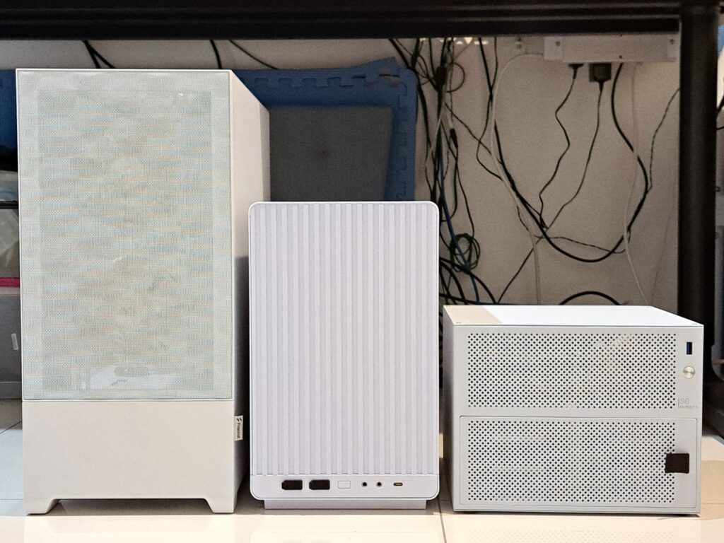
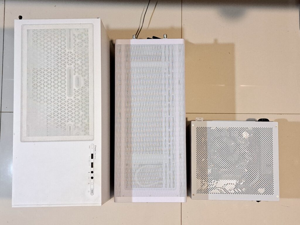
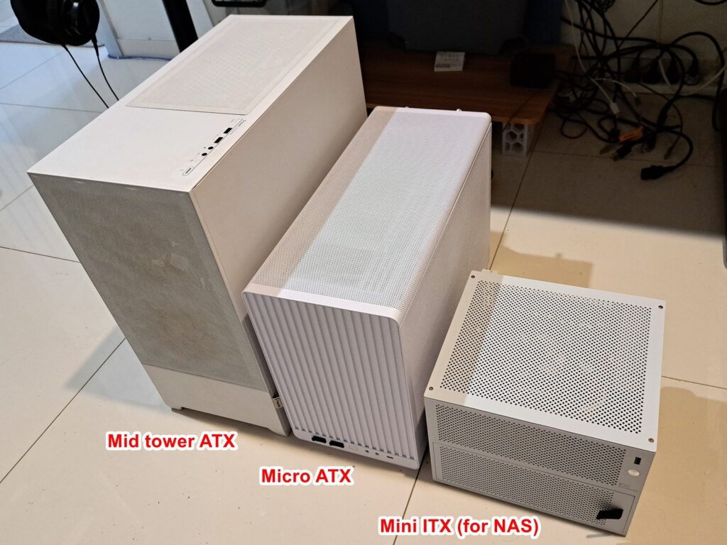
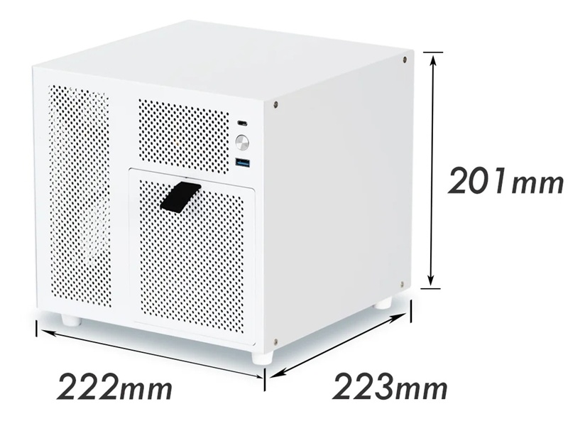
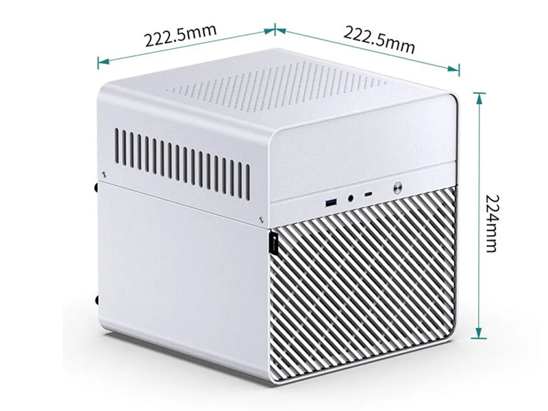
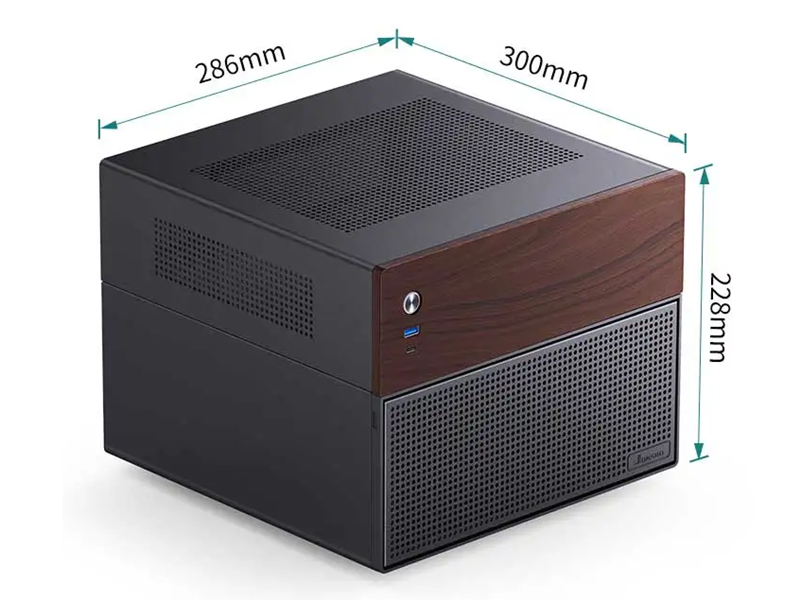
Below is visual comparision of different computer case sizes that I am currently using:
You can buy a gaming PC case a lot easier than for NAS. It is understandable. It’s like 100 persons buy computer, where as 95 is for gaming, 5 is for office use, and virtually zero is for NAS. Yes, I just make up the number. But I can see the market of custom NAS case is quite small.
The only place I can find NAS cases is amazon or aliexpress. Pretty much all of those NAS cases are made in china anyhow.
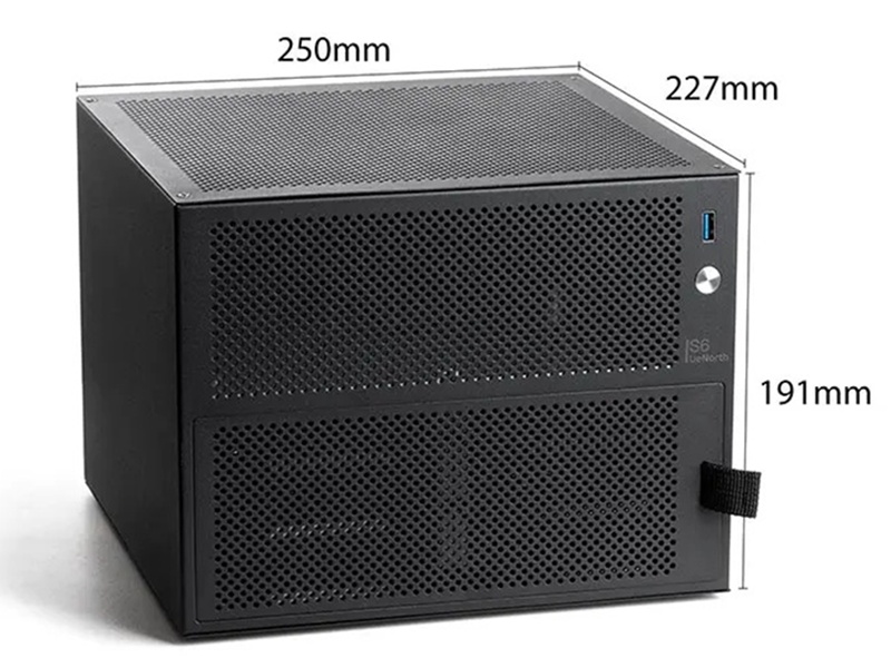
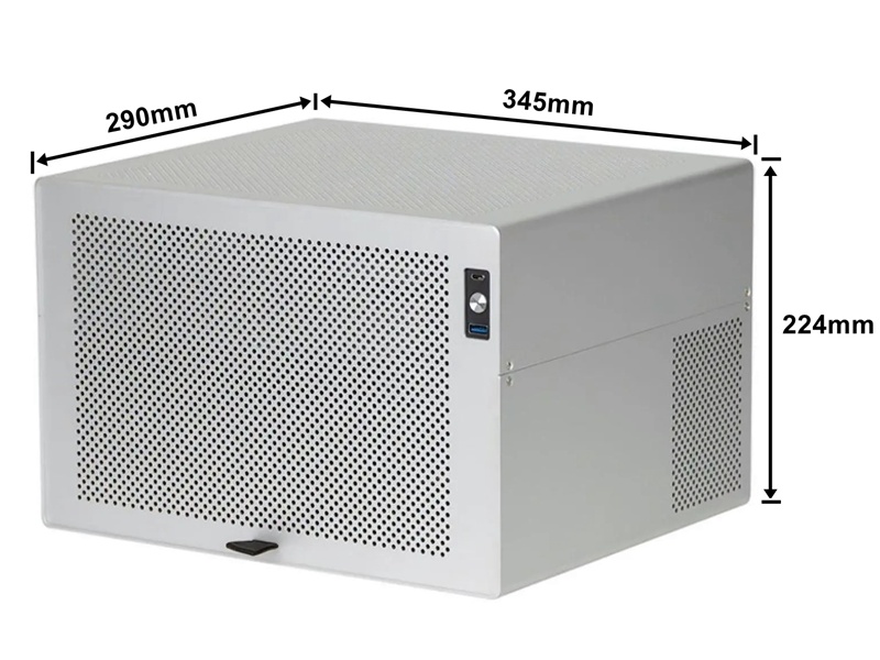
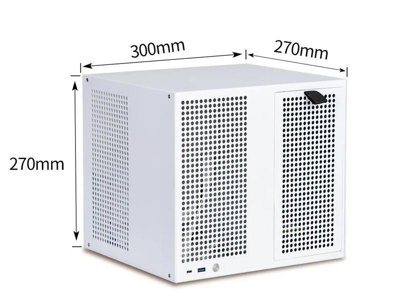
My aim is to reuse 4x 3.5″ hard drives I have for the NAS. There is no point to build the NAS but buy new hard drives along the way. So, 4-6 bays for 3.5″ hard drive it is. There are a few choices with theirs dimensions:
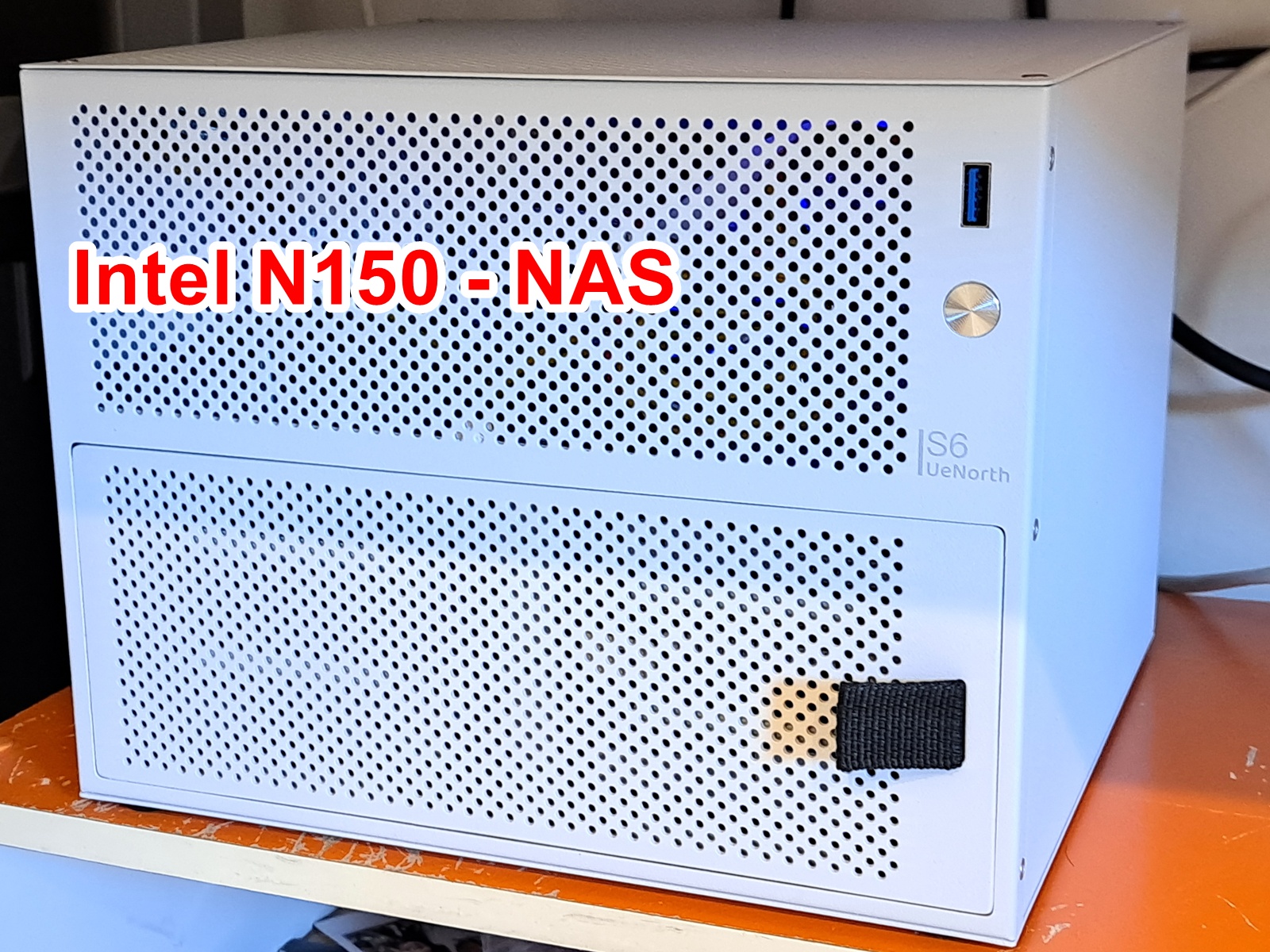
I decided to lock on UeNorth S6 NAS case instead of JONSBO ones. It is small enough and can hold 6 sata bays. I wonder if it is the same manufacturer of those constellation NAS cases (Aries, Sagittarius, Ursa minor), you know, North like in North star. I can see the design language of those cases are very much similar, like, the same power button, the same fabric tab to pull cover of the drive bays.
FIY, the NAS case is categorized as OVERSIZED SHIPPING, and it is extremely slow. It was over a month to get here in Australia.
Choosing the hardware: CPU and motherboard and PSU
I tried to design my own NAS case before, but failed. Actually, design a mini ITX case is not hard, as everything has dimensions, screw hole locations and all. The hard part is to design the removable caddy for 3.5″ hard drive. I already bought the parts for that but decided to give up. I don’t want to buy caddy for DELL server or HP server. My target is not really a budget NAS, but more like to build something nobody’s done before, something like almost impossible, such as use 2.5″ laptop HDD box to run 3.5″ HDD, say, a fun challenge for myself.
I originally had 2 plans:
USB HDD box + Mini PC (HP elitedesk) + 30A 12V PSU
ITX board (intel N150) + sata cable + old ATX PSU
Those HDD boxes are for 2.5″ laptop HDD that lacks of 12V power, but I soldered extra wire for 12V DC to be able to use with 3.5″ HDD and it ran just fine. FIY, 12v rail for the motor to spin the plates, while 5v rail is for logic board of hard drive. And yes, without 12v power, 3.5″ hard drive just won’t work.
My plan was to pull the pcb of those HDD boxes and solder extra wire to run with 12v 30A PSU. This to provide the missing 12v of those laptop hdd boxes
Some guy reported the mini PC can actually run off 12v instead of 19.5v. Afterall, the voltage will be dropped down to, say, 1.25v for the CPU or RAM, or 3.3v for NVMe drive… The only thing I can think of that could use 12v or +/-12v is the amp for headphone output. But still headphone amp still can be done with capacitor output and run on single 5v rail. Really, the buck regulator will drop down to target voltage regardless of input voltage of 19.5v or 12v.
The idea of attaching USB hard drives to a mini PC does have legs. Basically it is DAS + mini PC = NAS, where DAS is direct attached storage. I still have a bit of concern about 5v USB to power logic board of the hard drive. You know, USB is not the most reliable thing, we sometime have to unplug the USB to make it work again. I guess this is due to the 5v USB has to go through tracks and traces on the PCB and/or through mosfets on the motherboard, it is certainly not as reliable as 5v directly from the molex connector. So that I also had plan to have buck converters to have dedicated 5v rail feed to that usb box pcb.
After a few weeks sitting on it without any progress, I decided it’s best to use my time for something else, and I moved on with buying an Intel N150 ITX board from aliexpress.
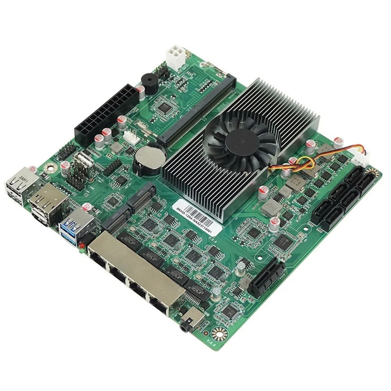
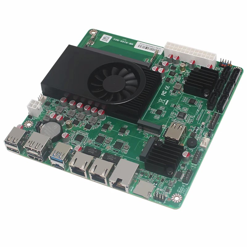
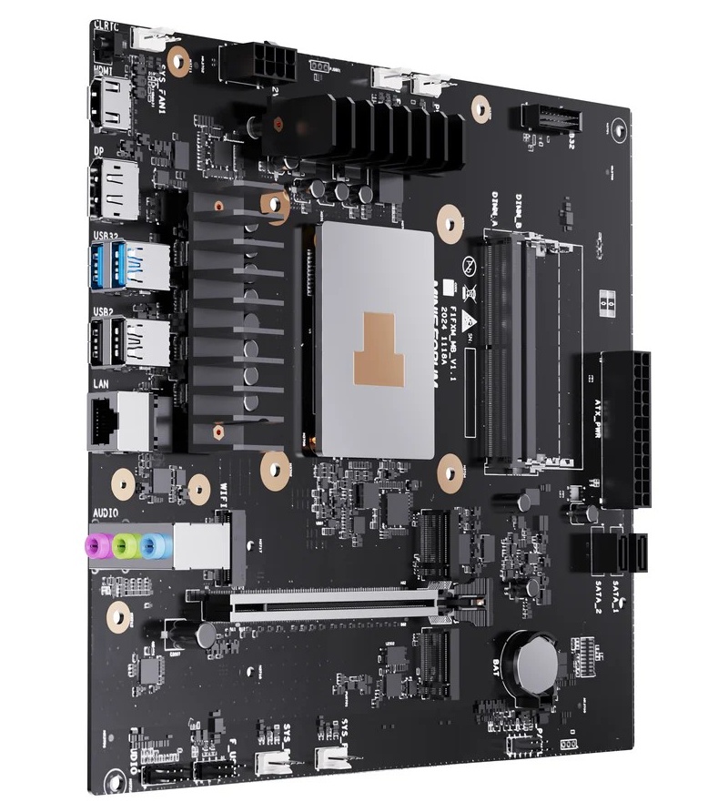
I was tempted to buy the board with 4x RJ45 port thinking I could build it as a NAS + router + managed switch. Doing more research, I find out that each RJ45 port ties to an intel NIC (network interface controller), which ultimately connects to the CPU via PCIe lane, probably. So, any routed traffic from 1 NIC to another is done in software, bummer!
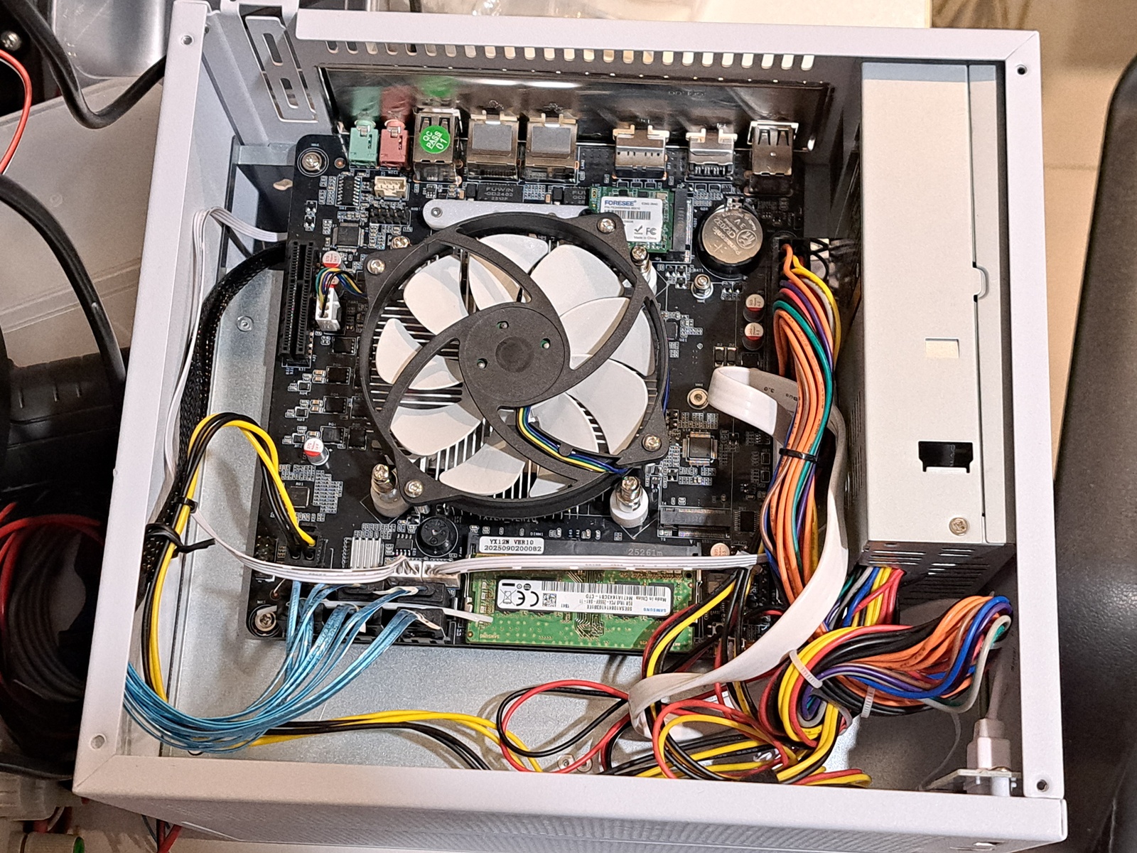
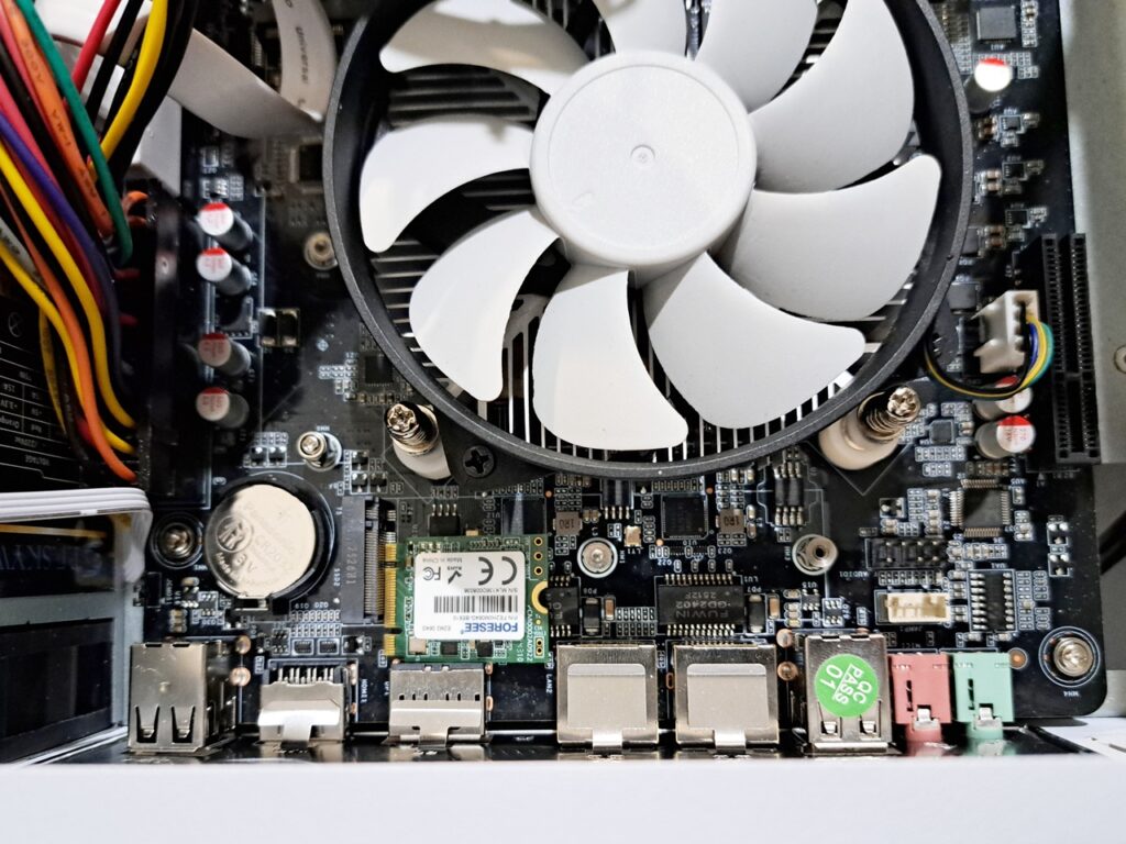
So I chose the cheapest option for N150 NAS motherboard: N150 NAS DDR4 Motherboard 6x SATA3.0 2x Intel I226 2.5G Mini ITX. It’s the one on the right. I went with DDR4 for availability because you can buy used SODIMM DRR4 easier than SODIMM DDR5. Ram rarely fails, a used DDR4 is still plenty good for my needs.
The use case for multi NIC computer like this is for multiple instances of virtual machine where each instance can have its own NIC and totally isolated, just like a completely different computer. I chose intel N150 for low power consumption, I don’t think I need to run any VM so I prefer a NAS with only 1 or 2 ethernet port but have plenty SATA ports for my hard drives. Additionally, my PC has only 1.0GBit NIC, and my switch is only 1.0GBit, there is no point having a 10GBit NIC for the NAS.The bottle neck is the HDD as it is about 120MB/s, the same speed of 1GBit ethernet. So I just pick the board on the right since I have some room for the board to fit inside the case.
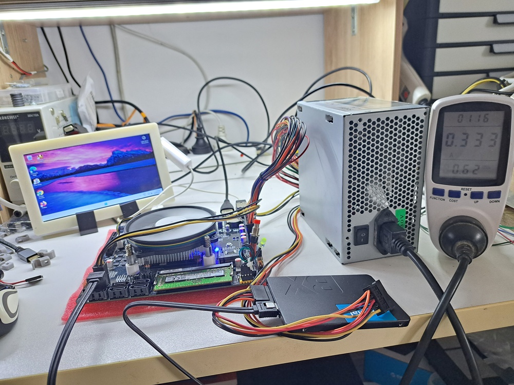
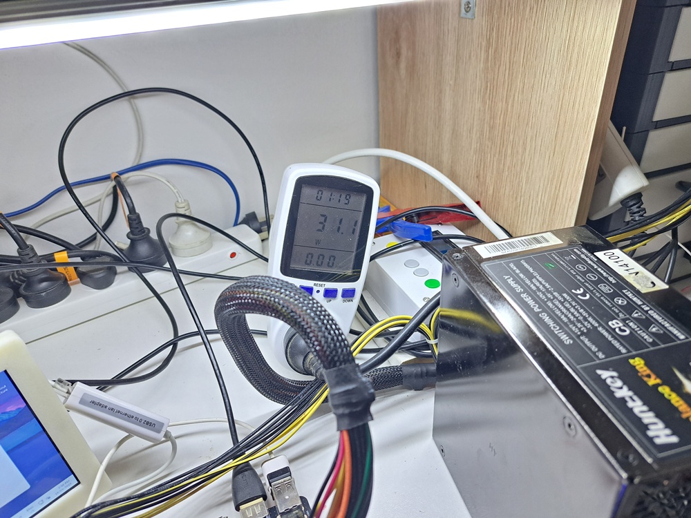
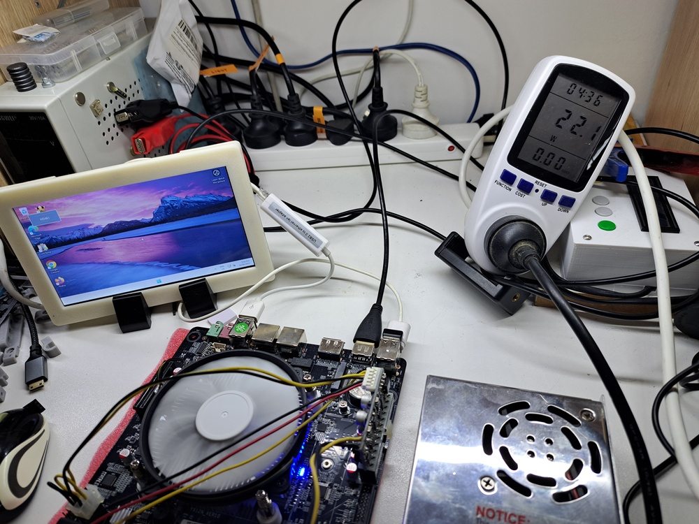
Running some power consumption tests yielded some interesting results:
The test bench: 8GB ram + Sata SSD + USB 2.0 to RJ45 adaptor + 7″ LCD powering from USB port + running windows 11.
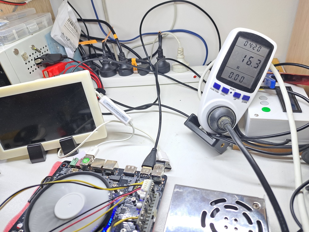
While the setup with ATX PSU pulled about 31w at idle and around 53w at full load, the setup with 12V-20A switch mode PSU + Pico ATX PSU only took 22w at idle and 42w at full load. When I unplugged the USB power for the mini LCD, power consumption fell down to 16w. The math is about 70% efficiency (= 22w / 31w * 100%) for ATX PSU if we considering 12v-20A psu setup was 100% efficiency. So the actual efficiency is lower, about 50-60%.
To be fair, ATX PSUs are designed to be highest efficiency when it is around 50-80% of max load and 31w is only about 6% load of 500w PSU. That is why the efficiency is terrible at light load.
For the test system above, a 150w PSU is good enough. But, there are 6 sata bays for 6 hdds, each hdd can take extra 18w, make it around 108w. The maximum power consumption of this NAS would be around 170w. To be safe, The PSU for this NAS should be 250w or higher.
Rule of thumb when choosing power supply for electronics: choose the power supply that can do at least 30% more of maximum load of the system. It’s just that the higher wattage, the pricier they get.
I bought 350w flex PSU for this NAS. It costed me only AU$45 shipped from aliexpress.
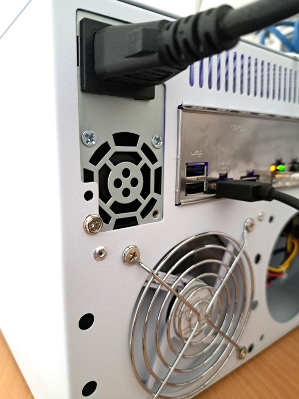
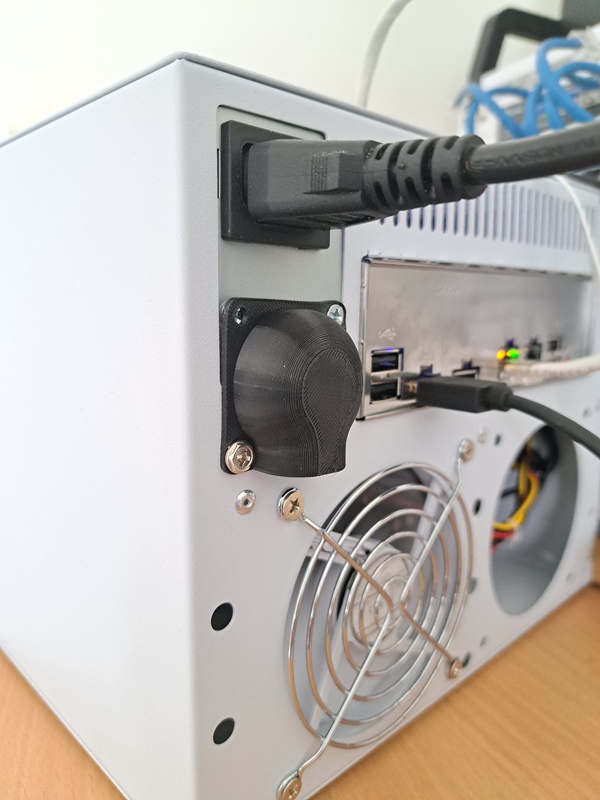
Of course, the cheap flex PSU doesn’t have fan speed controller to limit the noise of those crazy high speed 4020 fans. Those fans can spin very fast 5000rpm to 18000rpm. This high speed fan generates irritating high pitch noise, that I have to print a fan shroud to eliminate that noise
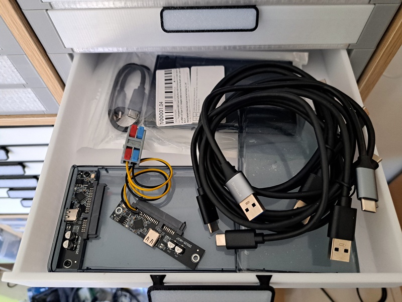
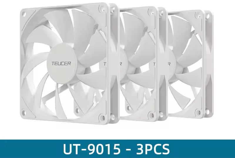
The case came without any fan. It was expected, so I bought 3x 9015 fan for it.
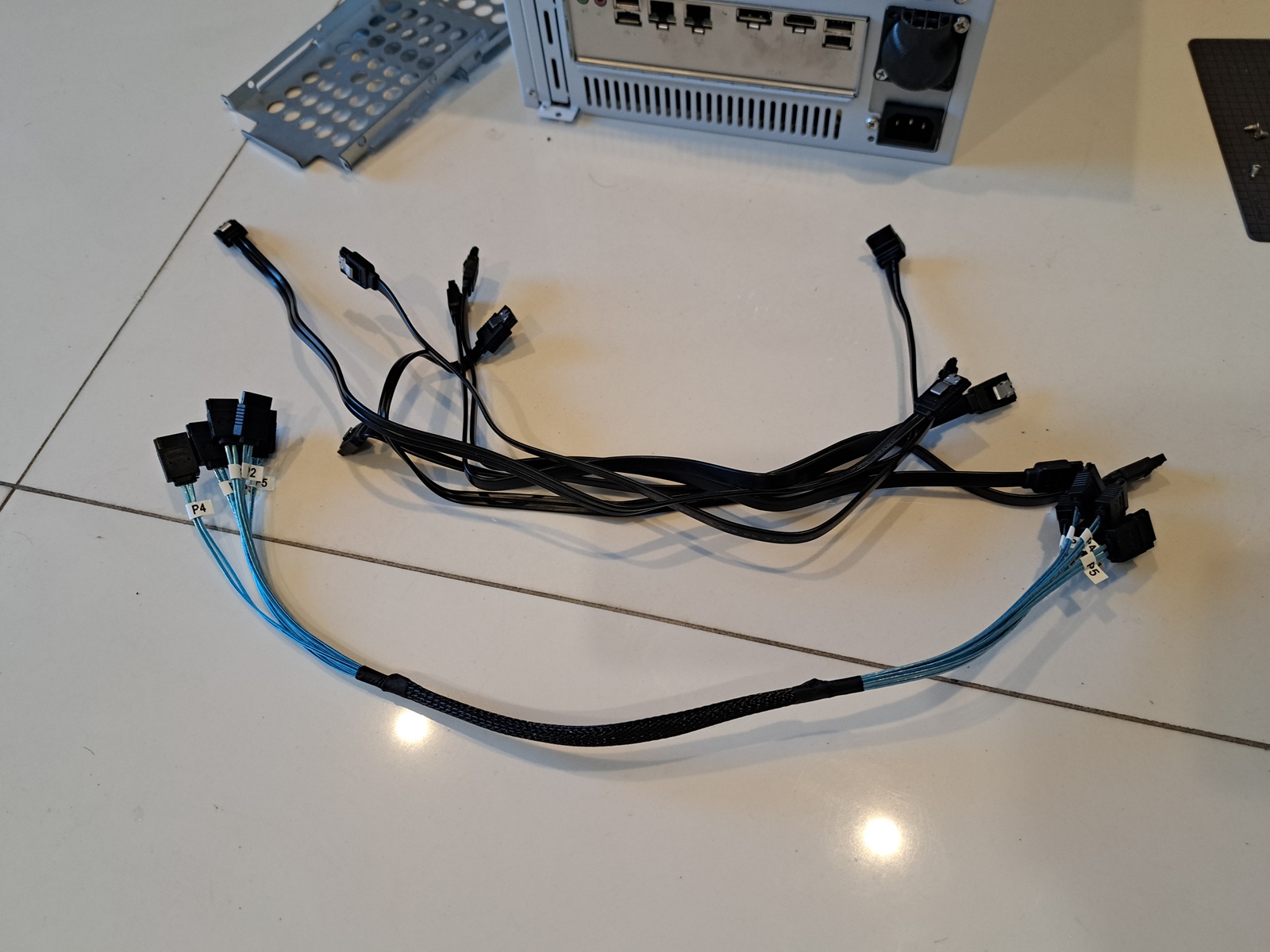
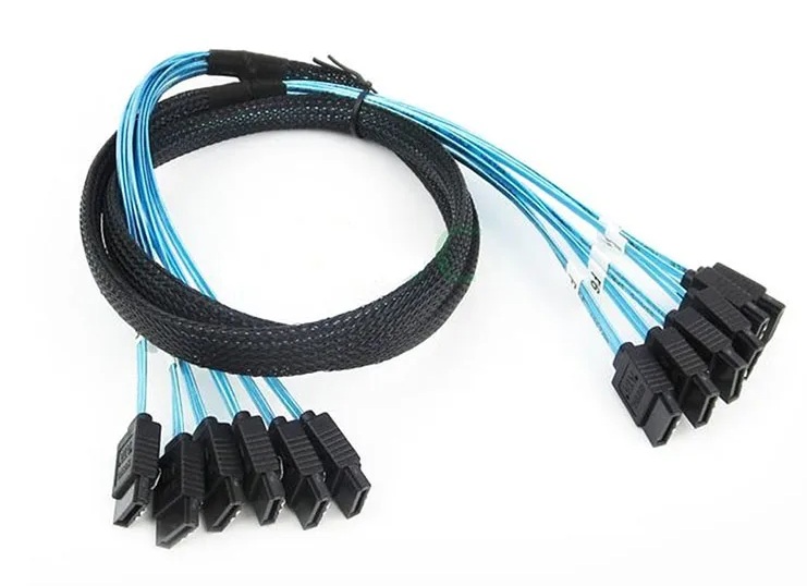
I also bought about 10x sata cable. Turn out those normal sata cables are too stiff to use in this tiny case. So that I had to buy sata cable bundle. Before I build this NAS, I didn’t know there is such a cable bundle like this.
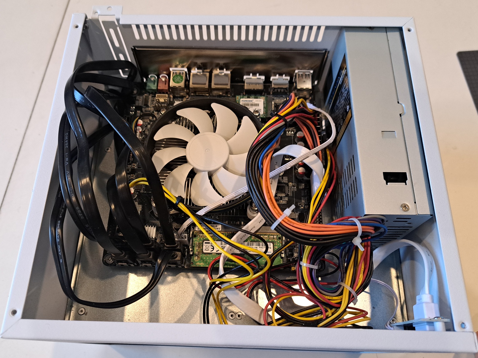
The intel N150 max TDP is 15w, it can be entirely cooled by passive heatsink. But since there is no exhaust fan in the upper half of the case, hot air will just be trapped and circulated around the CPU fan instead of going out of the case. After consideration, I flip the CPU fan from blowing down the CPU to blowing upward. So that a little bit of hot air will be forced to go through vent holes on the top panel and thus fresh air will get in through the front. I could design duct at the CPU fan to get more air come out easier, but meh.
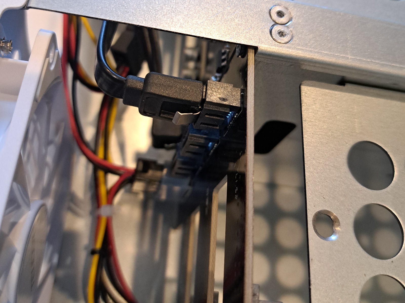
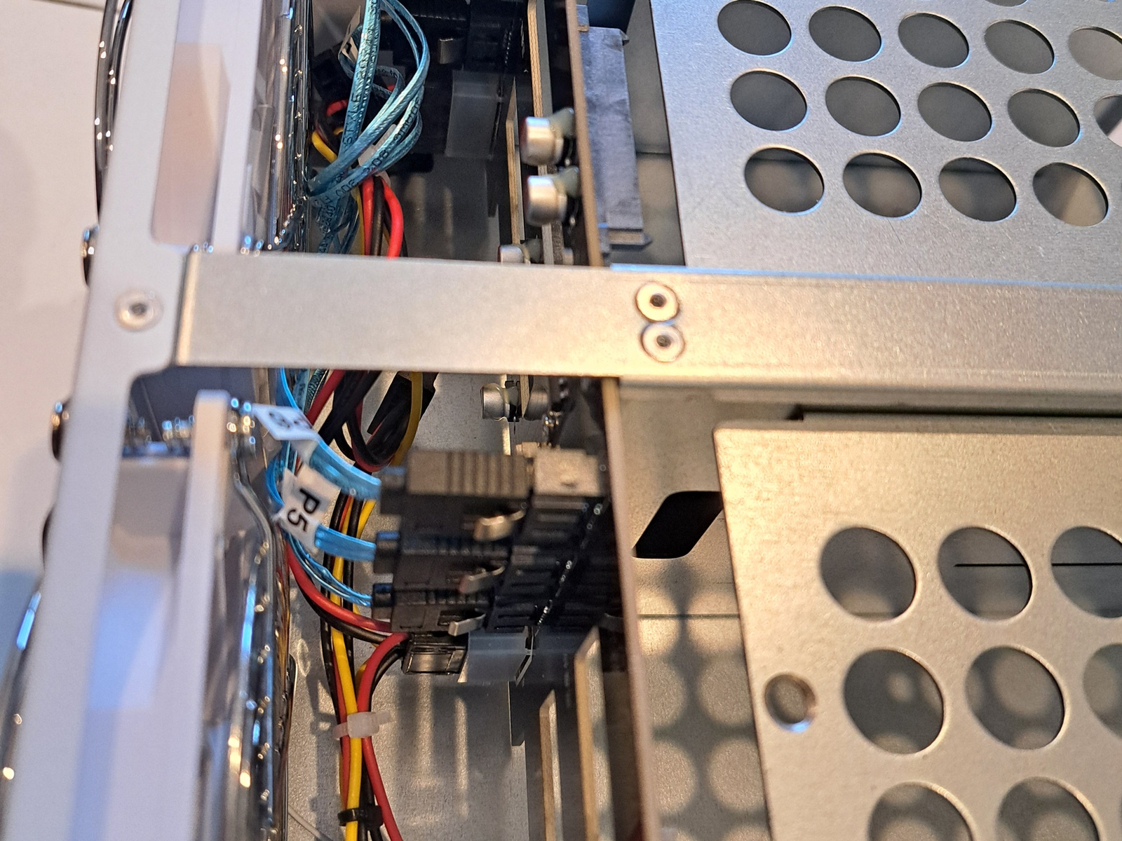
The case is laser-cut so that the edges are very sharp. It is understandable with low volume product to be laser-cut rather than made with punching or stamping machine. I had to run sand paper over all edges of the steel hdd trays. It just is too sharp, almost like razor sharp. It cut me when I tried to plug in those sata connectors at the backplane pcb.
The process of assembly everything together is quite straight forward:
Install the motherboard
Install the PSU
Run power wires to the bottom half
Run sata cables to the backplanes
Cable management
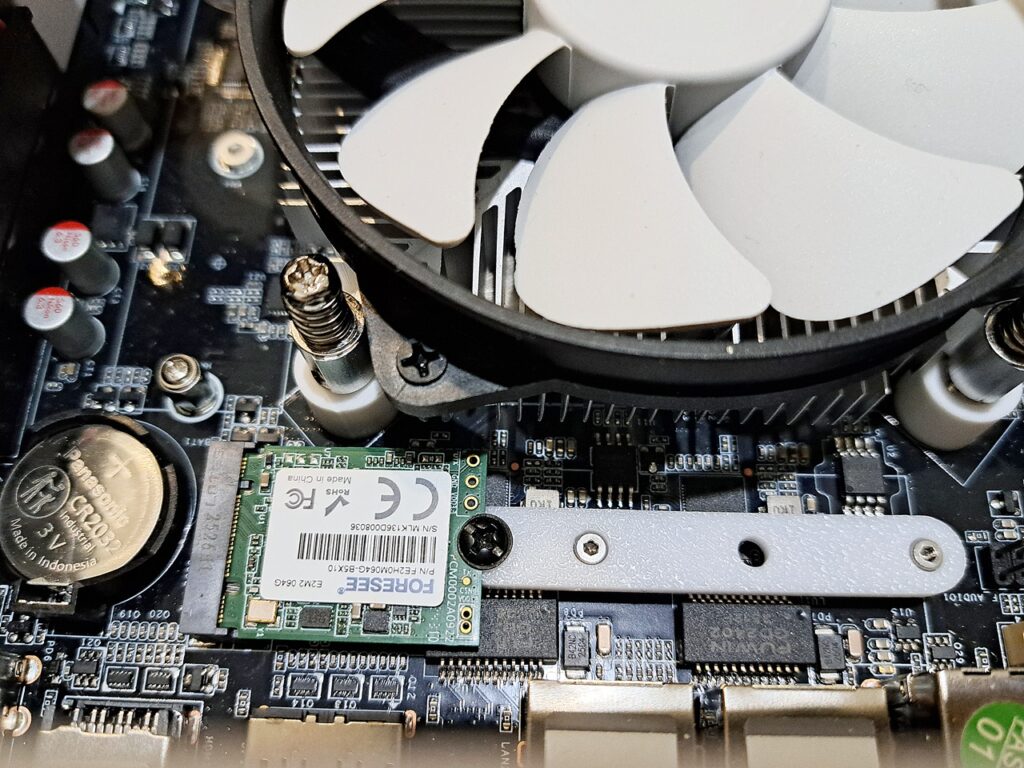
I have a 64GB NVMe 2230 that I want to use. This drive was from a steam deck. It’s quite useless for everything else except it’s perfect to use as boot drive for the NAS. I just have to design a bracket for 2230 to sit in 2280 and 2242 slot.
If you have the same problem, you can download the 2230 bracket here
Here comes the troubles : the software for NAS
My needs from the NAS is pretty simple:
Backup my work data regularly
Only backup if there is any change to the data
File server to store movies
My works are almost about firmware for microcontrollers. And the firmware rarely changed, unlike PC software that needs constant bug fixes. Once the firmware is at working state there won’t be much change. It could be only one minor change after 2 years or so. So that, backup everyday is just a waste and make it a lot harder to trace back where was the change was made when going through tons of archives, like 365 archives a year if I backup everyday.
Of course, once in a while I should copy the archives into a USB drive and keep it offsite for extreme measure.
My first try was trueNAS. It is generally very good, the web sysadmin to help you to control every aspect of the NAS is very straight forward and intuitive. But it requires to format the hard drives into ZFS. I have no problem with formating 1TB drives, but I also have 6TB drive that 70% full of movies that I don’t have any mean to dump those data to in order to format this drive into ZFS. Yes, it was currently NTFS.
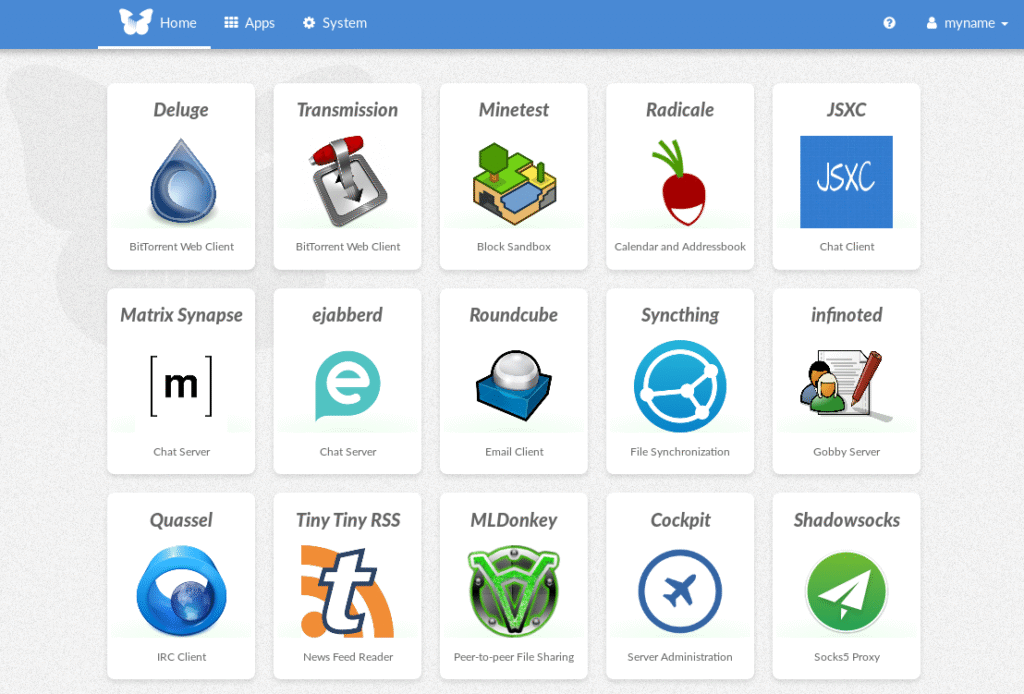
While experimental with trueNAS, I discovered cockpit. Which is exactly what I need. I don’t want to fiddle with command line for everything, too much to learn, so a web sysadmin interface is like a godsend for me.
So I decide to have linux + cockpit + cockpit file sharing as my base software for the NAS.
Then I tried debian 13, Ubuntu server 24.04.3 LTS. I also tried some desktop flavour like EndevourOS and KDE neon for this NAS. I know, I know, it is suppose to be a headless server, why would I want a distro with desktop environment? Debian 13 inet installer does have an interesting flavor: freedombox to be installed along. It’s like the desktop environment but on the webpage for the headless server, neat!
Freedombox interface
Heck, I even tried to install Arch, but the installer just boot into bash shell. There was no GUI, no instruction. I was lazy and gave up on Arch
When testing freedombox, I tried install cockpit and config samba there but no joy, windows 11 couldn’t see samba share whatsoever. I spent a week trying debian 13 and ubuntu 24 with cockpit, you know, following instruction to install from the website but still there is no sign of life from windows 11. So, I had to get my hand dirty and dig deeper. I had to use a port scan tool, which I collected since 2012 and it was flagged by Windows Antivirus immediately the moment I unrar the file. Well, I’ve been using this tool for years, long before windows 10 without problem. Then I realized that port 139 and port 445 was not accessible from windows 11 machine. And sure enough, samba wasn’t installed along with cockpit file sharing even though samba was listed as dependency, as it should install all dependencies along with main package right? Then install samba for real this time and also install wsdd (web service discovery host daemon) just to place nice with windows. Windows 11 does work with samba now.
Then I go ahead and install cockpit identities, cockpit navigator. But some how I broke cockpit while manually compile and install those. Do more reading, I realized one of those plugin only supports up to ubuntu 20!
Up to this point, I already got my hand dirty and dip deep into linux command line world, like recompile those packages from source to install them, mostly still follow instruction though. I couldn’t fix the cockpit I broke, so I decide to install debian 12 and start fresh. Now everything works the way it should be.
Lesson learned: do not install the newest version of linux for server, as too many packages are changed and it could break the software you want to use. Stay one or two version behind the newest one for a server. Say, debian 13 is newest at this time of this post, just use debian 12 instead. You have to give those software a few years to catch up with newest release of the OS. You know, linux world is mostly free, most of them are doing this at their spare time. Unlike microsh!t, its programmers get paid fulltime just to break the old trusty windows we used to use.
On some side note: I did run KDE neon on a hp elitedesk mini pc a while ago until I gave that mini pc away as a part of firmware flashing machine. Yeah, instead of spending time, a lot of time to setup the flashing environment on customer PC, I just gave him the mini PC and that’s that, quick and easy.
So this is the list:
Debian 12
Cockpit
Cockpit identities
Cockpit Navigator
Cockpit file Sharing
Samba
Wsdd
Transmission
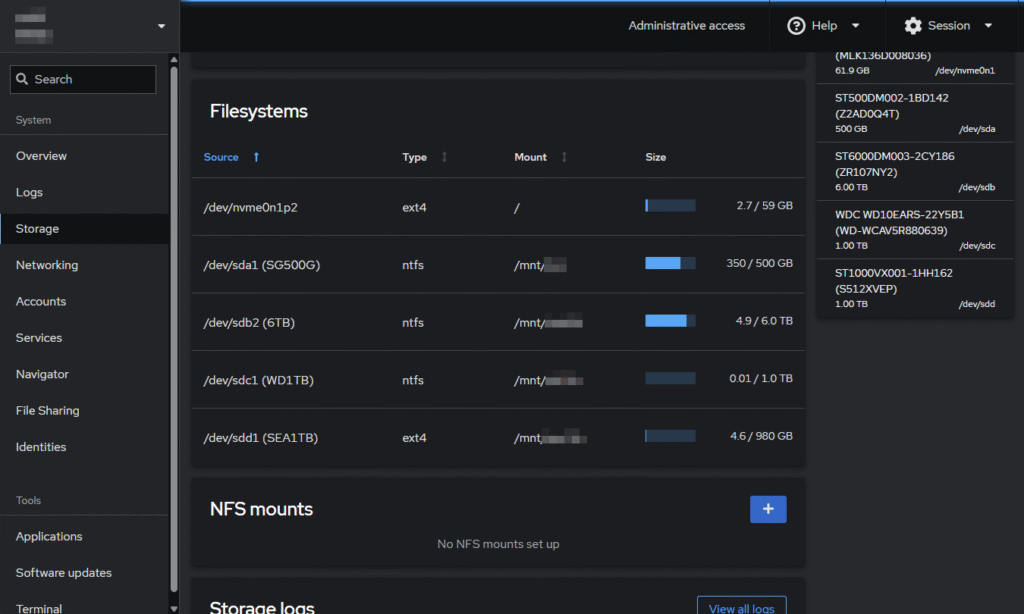
And my NAS just accept NTFS without any complaints, unlike trueNAS which requires to format the drives into ZFS.
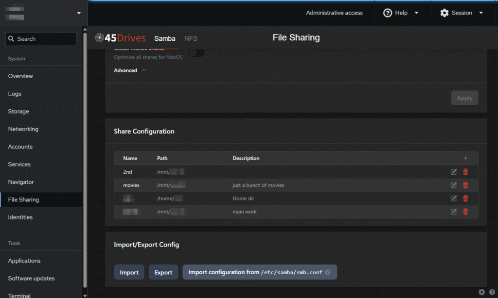
When I insert a new hard drive, I just have to mount it and assign a share to the location I mount. I can easily add new share for guest, a lot easier than mucking around with “sudo nano /etc/samba/smb.conf”
Backup script to backup data
As mentioned before, I need to backup data regularly but only backup if changed. So I wrote a shell script to do this job
ShellScript
#!/bin/bash# This script will backup a <source folder> to <sync folder>, checking for changes of subfolders# If there are any, it will zip each modified subfolder into a separated timestamped archive# Dependencies: p7zip, p7zip-full, rsync, pv (pipe viewer)#Location of Source foldersource_folder=/mnt/sdb/WORK_DATA/#Location of Destination folder that you want to backup to (existing extra file could be deleted)sync_folder=/mnt/sdc/SYNC/WORK_DATA/#Location of zip archives if there is any changes between synced folder and main folderarchive_folder=/mnt/sdc/ARCHIVE/WORK_DATA/#Log filelog=${sync_folder}../../backup.logcurrent_dir=$PWDecho-e"\n\n"echo"-----------------------------------------------------------------------------------------"echo" This script will backup folder WORK_DATA from SEA1TB hard drive to WD1TB hard drive "echo"-----------------------------------------------------------------------------------------"echo-e""mkdir-p ${sync_folder}mkdir-p ${archive_folder}echo-e"--------------------------------------------\n$(date +'%Y.%m.%d %H:%M')\nStart Backup ${source_folder}\n" >> $logecho-e"Destination: \n ${sync_folder}\n ${archive_folder}\n" >> $log#Move to [source folder] to get a list of subdirs to sync_list.txtcd$source_folderfind.-mindepth1-maxdepth1-typed-execbasename{}\; >${current_dir}/sync_list.txt#Move back to current foldercd$current_dir#Loop through all subdir of [source folder]whilereadsubdir; do#Create folders again just to make suremkdir-p ${sync_folder}$subdirmkdir-p ${archive_folder}$subdir#echo "checking for different between source and sync"diff--brief ${source_folder}$subdir ${sync_folder}$subdir > /dev/nullif [ $? -eq 1 ]; thenecho-e"- Item $subdir has been modified since last sync"#syncingrsync-avh--ignore-existing--checksum--delete ${source_folder}$subdir ${sync_folder} | pv-F" Syncing... %t" > /dev/null#zipping7za-t7z ${archive_folder}${subdir}/$(date +"%Y.%m.%d_%H-%M").7z ${sync_folder}$subdir | pv-F" Zipping... %t" > /dev/null#loggingecho-e"- $subdir changed -> synced + zipped" >> $logelseecho-e"- Item $subdir in synced drive is the same"echo-e"- $subdir not changed -> not synced" >> $logfidone < sync_list.txtrm ${current_dir}/sync_list.txtecho-e"\n\n" >> $logecho-e"\nJob done!\n"
So, my main data is in /mnt/sdb/WORK_DATA/ and a complete identical mirror is at /mnt/sdc/SYNC/WORK_DATA/ on a different drive as a backup. I also have archives stored in a third location /mnt/sdc/ARCHIVE/WORK_DATA/ which has zipped files. The script won’t zip the whole WORK_DATA folder, but zip each individual subdir into a zip file only if there is any change in that subdir when the script runs.
Let say, I have
/mnt/sdb/WORK_DATA/kicad_project/ to store all PCBs I ever work on
/mnt/sdb/WORK_DATA/stm32_project/ to store all firmwares stm32 micros
/mnt/sdb/WORK_DATA/esp32_project/ to store all firmwares stm32 micros
and so on…
So in ARCHIVE folder I’ll have
./WORK_DATA/kicad_project/
2025.11.10_07-54.7z
2025.11.11_09-20.7z
./WORK_DATA/stm32_project/
2025.11.10_07-54.7z
./WORK_DATA/esp32_project/
2025.11.10_07-54.7z
kicad_project archive folder has one extra file, because I only made changes in this folder between 2025.11.10 07:54 and 2025.11.11 09:20 while others folders are the same as before.
This is very much the same as CCTV camera only records when there is movement on the screeen.
Basically, I can put those 3 locations in separated drive to ensure highest chance of survival if one drive fails or acidental deletion or whatever. You know, nothing lasts forever, everything will fail eventually.
For now, I just put both mirrored data and zipped backups in the same drive, it doesn’t matter much. I do copy the archives to USB drive every now and then for extra safety.
Then next step was to setup cron job to run this script how frequently I want it to be. This is as easy as running crontab -e to edit the cron job config.
The total budget for this custom NAS
intel N150 NAS motherboard — $205
SODIMM DDR4 8GB — $25
UeNorth S6 case — $108
Flex PSU 350w — $44
6x Sata cable bundle — $12
3x 9015 fan — $17
64GB NVMe — free
4x 3.5″ hard drives (6TB, 2x 1TB, 500GB) — free
The total cost is AU$411, not as really in the budget that I thought it would be, but sure it isn’t bad compare to Synology NAS or alike. If I include the cost of the hard drives, it would rise up to about AU$800.
Compare to prebuilt NAS that has only about 1 or 2GB ram and run on dual core ARM CPU @1.7GHz, it’s pretty much in the ballpark of AU$400 to AU$600 to this one.
Certainly, this custom NAS cannot compare to those of one notch better, like MINISFORUM N5 AI NAS (AU$1700) or UGREEN NASync DXP6800 Pro (AU$1655). Those NAS have better CPUs for sure (intel i5 12th gen or Ryzen 7 255). Sure enough, those NAS will be a lot better in heavy tasks like plex transcoding 4k video. But for me N150 is well enough for my use and totally worth it. And it also doesn’t burn too much of electricity.
Disclaimer, this story is just made up. Sorry for the language in this post, I really have some beef with some guys who attack a few persons whom which desparately disagree with BBL.
The Weird Story
There is a boy, let call him A, having a relationship with a girl B. The girl B promised a lot of things: buy me presents, buy me this buy me that and I’ll have s3x with you then I’ll do this do that for you (let say Kama Sutra styles). The boy A bought a lot of things for girl B, but then the girl B changed her mind she woundn’t do XXX style with him as promised.
The boy called her out for going against her promises, but then the girl went on “tweeter” and gaslighted the boy and say she would only have s3x in her bed room with her security camera on, that is for “his protection”.
Then the girl force the boy to contact her using only “wechat”, which is a software of her father’s company, she wouldn’t use “telegram”, which is a free opensource software. “Telegram” had many feature the boy likes and a special feature that can cross-talk to wechat but then the girl ask her father to cut off cross-talk from telegram. So now the boy had to use “wechat” only if he wants to communicate with her.
Here is how he communicates with the girl: he opens his phone, start telegram, type in the message that well formated to his heart content, then copy the message, open wechat, paste that message into wechat and hit send. So yeah, the boy felt frustrated, desperated, and finally gave up.
There is a person C, a bystander, who probaly has some benefits from “wechat” or doing business on “wechat”, I don’t know. This person C mocks and laughs at boy A whom which aleady threw white flag and tweeted that he gave up the relation ship with girl B.
There is also a guy D who also really likes the girl B. This guy D doesn’t care about the girl’s “security camera” recording them “having s3x”. He says, it doesn’t matter as he is nobody and how can girl B hurt him with those recoding? So yeah, as long as the “s3x” is good, everything is fine. And so he keeps doing what he wants to do with the girl.
The story ends here. Only time will tell if there is any development. Meanwhile, the girl B keeps inventing multiple kama sutra styles, and they actually look good and perform good.
I feel sorry for boy A, and yes A is for naive. I don’t condemn girl B, in spite of B as in bitch. It’s how she does her bussiness, I guess. But being mean and mocking a walkaway, just like person C did, is what I can’t stand. So yeah, C is for cunt. I understand C is currently making good money on “wechat”, so “wechat” going down means he loses money. He probably feels threaten by someone’s remotely talking bad about “wechat”. And lastly, D is for don’t care.
The Translation
This story is weird, I know, but just replace some words here and there and it would make sense:
girl B
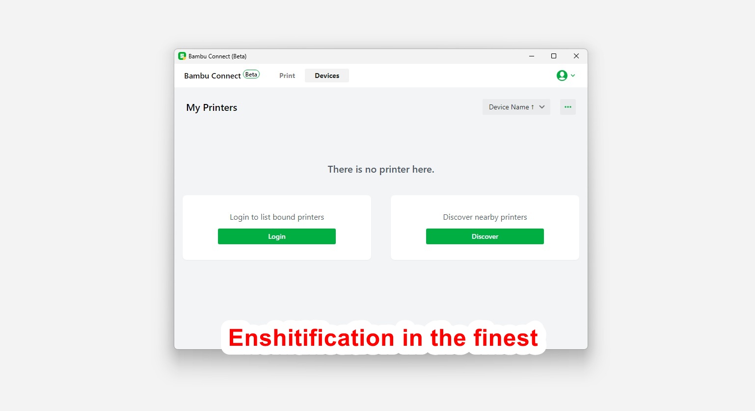
Bambu Lab
having s3x / kama sutra style
3D printing / 3D printer/ Terms of service
security camera recordings
BBL cloud server storage in China and by Chinese law, it will be handled to the CCP if asked
wechat
BBL cloud / BambuStudio/ Bambu Connect
telegram
OrcaSlicer
tweeter
BBL forum / BBL blog
person C
BBL fanboys who keep defending BBL and mocking people about raising concerns
guy D
me, writer of this blog
The Verdict
Before the Bambu Connect happened, I was the guy D. But now, my P1S stays behind firewall with old firmware 1.07 to use with OrcaSlicer. It will stay like that until I squeeze out the work equal to AU$1500 investment. Then it is to the bin.
Let say, I loved (past tense) BBL printers. They are fast, accurate and super convenience compare to similar price range. But BBL broke the trust in me. The ship has sailed and it won’t come back.
I know I am nobody, the sales gain by individuals like me is just a small fraction of printer sales, say 0.001 per cent, so that my voice has no weight, just like shouting out in an empty room and no one hears. So, I suck it up and move on.
It is true that BambuLab is very smart to target the masses (the Average Joe) and bring them the convenience of handy app. That is just with a few taps on the phone, and voila, a success 3D print without the long hours tinkering or steep learning curve of 3D printing.
Well, I am not jealous with the money BBL make. I just feel bitter with years I’ve spent tinkering and building 3D printers but the prints didn’t look as good as what BBL printers can print. And now people having a perfect print and take it for granted. Those kind of people who would blame a 15 minutes print failure on the designer who spent days to perfect the model. That was the reason I removed all of my designs on printables and thingiverse. I just can’t deal with those ungrateful people. I’ll probably do the same on makerworld.
Okay. Up until now, I’ve been sharing my knowledge about 3D printing and help people with 3D printing in BBL forum. I will stop doing so.
If not for the only frigging app I need for work, FUsion, that stops support for windows 10. No update for a cloud based app means no more access to cloud data. Yes, FUsion means Fk-You-sion. I start the fusion by hitting [win] + [F] + [U] + [enter]. That is how much I hate FUsion and Windows11. It was fusion 360 and I used to hit [win] + [3] + [6] + [0] + [enter] using the numpad. I wish I could change the CAD software, but an old dog like me can no longer learn new trick.
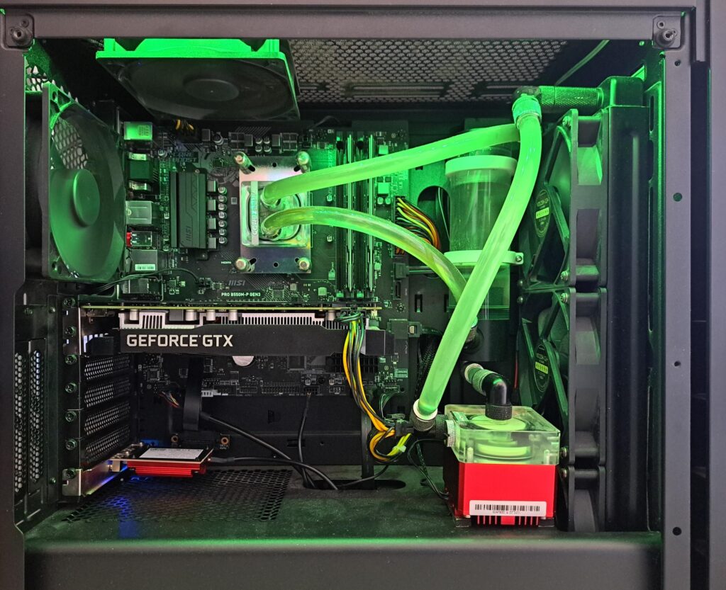
Windows 11 is much sluggish compare to windows 10. That was my first impression on my old PC: Ryzen5 5600G + 16GB RAM + 1660 super. That was a decent computer not as low budget as it seem.
I got bitten by bitlocker, twice, until I realized bitlocker was enabled by default without telling that during fresh installing windows 11. Yes, lost data and banging my head thinking it was because of hard drive failure. Bitlocker won’t be enabled if you are upgrading from Windows 10, that with bitlocker disabled of course. My bitter experience tells me, it is just a frigging ticking time bomb. Imagine that you store 1 bitcoin in the secured usb stick and somehow you lose the key to unlock the usb stick, yeah that was my feeling, except I am not that rich.
I understand that TPM is essential for bitlocker, but I don’t want bitlocker in the first place so why do you make it compulsory to install windows 11? Is that the guaranteed way to f*ck up my data when the motherboard fails? Then people will laugh on you because you didn’t backup the keys inside TPM for that worst case scenario.
Why there is a tickbox on the icon of a file? It just confuses everyone, both new windows users or veterans.
Why would I need a microsoft account in order to login my PC. Why would I have to jump through hoops and loops in order to login windows the first time without MS account. Are you that data hungry that you want to harvest data from every single windows user? Why would you keep telling me to log in with ms account?
Why would you pop the backup reminder screen after every single windows update to sell 365 subscription package? Are you that saleperson who’s so clingy to a customer desparately? Why would I want one drive since I have my own server and backup server?
Why you keep deleting my administrative share after every single windows update, which happens only after a few days. This was so annoying to the point I gave up administrative share and built a dedicated NAS to share file around my homelab instead. Are you deeming administrative share unsecure and force the user doing your way, just like how Bambu “BS” controversy about bambu connect. FIY, “BS” is both Bambu Studio and bullsh*t at the same time in my vocabulary, or should I say “BS BS” instead.
Why would I have to click on show more options on the popup menu which supposes to be more convenience? Do you understand the copy, cut, paste icons are a lot harder to spot and click with 2K monitor even though the monitor is 29″, not to mention portable 11″ monitor with the same 2k resolution.
Why would I have to jump through hoops and loops just to disable a NIC or change DNS settings? What’s wrong with the old school control panel so that you are phasing it out?
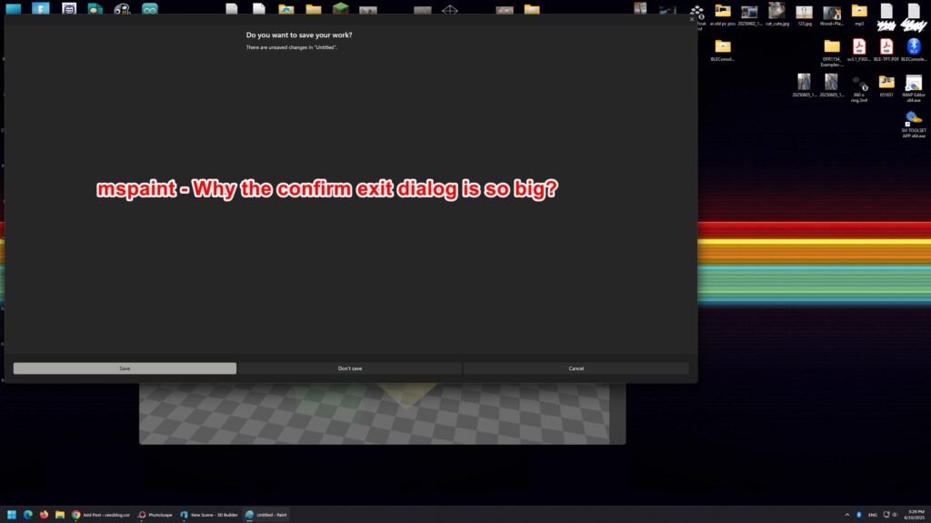
We use mspaint because it is simple, it is pixel-based editor. Why would you keep “upgrading” it the worst way possible? “Upgrade” here is in air-quote! Why would you assign a moron programmer to “upgrade” mspaint like that? If I want AI stuffs, I would go with photoshop or go cheap with MS photos app. Isn’t photos app is not enough so that you have to bring AI stuffs into mspaint? When I think of free solution to do with photo editing for website or uploading 3D designs to printables or makerworld for example, such task as adding text, adding arrows, descriptions… to the photo, my first thought is Photoscape v3.7 although it doesn’t have AI sh*t like background removal. You want the photo as real as possible because people hate AI generated photo.
Why would you remove some useful apps, like 3D builder? It was very useful app. It did help me a lot during my first days with 3D printing stuffs. It seems like you are trying to get rid of traces of windows 10 out of windows 11. Do you want to erase the existing of windows 10 that much?
I’m still thinking about #13, might edit the post later. For now the obvious reason is to make the title sound like “13 reasons why” show series or the song “10 things I hate about you”. So, that’s that.
As recently, my 5 years old PC’s showing age: bsod and crash during web browsing. It was R5 5600G pairing with 1660 super, a mid-range budget build at the time. I don’t know what causes the crash, but I am not really interested in finding out. It’s served me well during the years. So yeah, let put it to rest and build a new PC.
Choosing self-built PC instead of pre-built PC
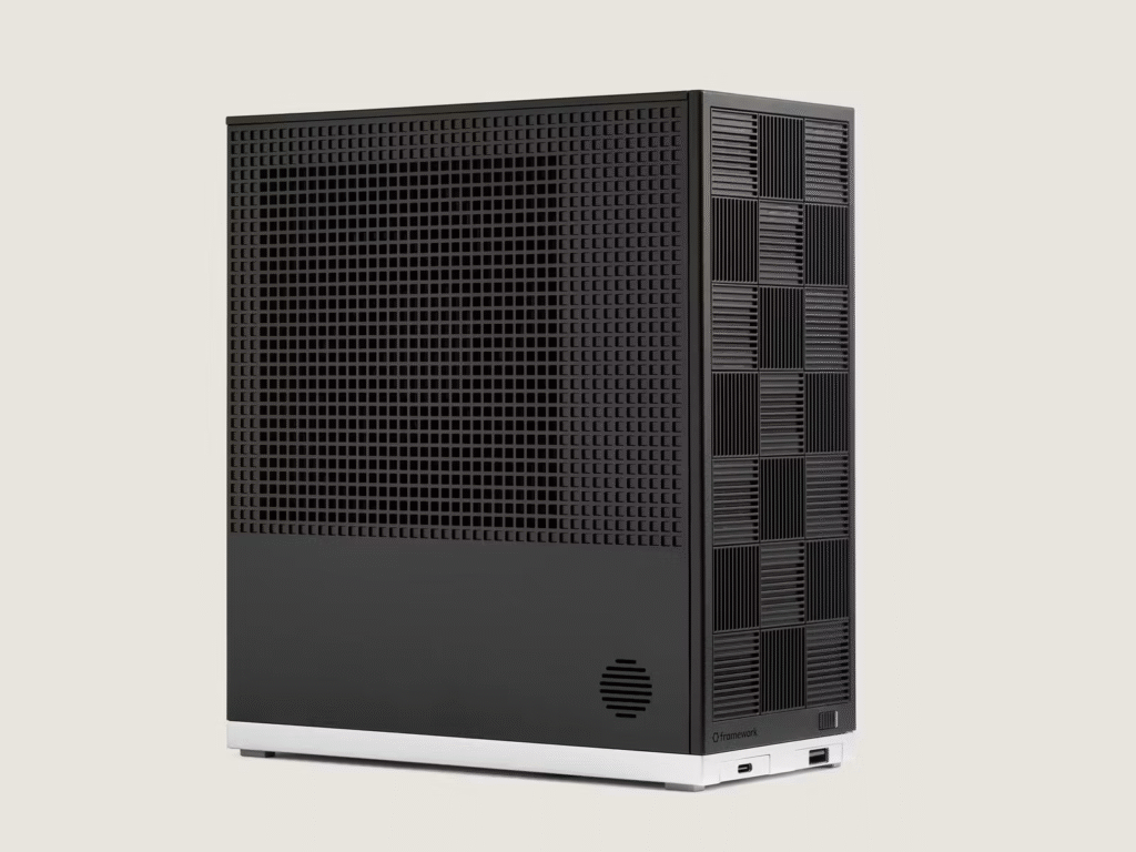
I’ve been contemplating for almost a month what CPU for my next PC. Thinking Strix Halo would be the best as the iGPU (8060s) is quite on-par with mid-tier discrete GPU, the like of RTX 4060. But the price is quite steep, such as Framework desktop Max+ 395 – 64GB for ~AU$2900 minimum. Let round it up to AU$3000 as you have to buy accessories and stuffs as well.
I don’t care much about 10-20% CPU processing power difference, it still is huge improvement over my old PC. My work is about 2D and 3D cad (kicad + fusion) mostly. I also do some light gaming for entertainment.
As for the budget AU$3000, I could build a better PC compare to Strix Halo. Just some rough estimate for AM5 R7 9700X system:
600 for GPU
600 for CPU
300 for Motherboard
300 for RAM
300 for case + PSU
300 for SSD
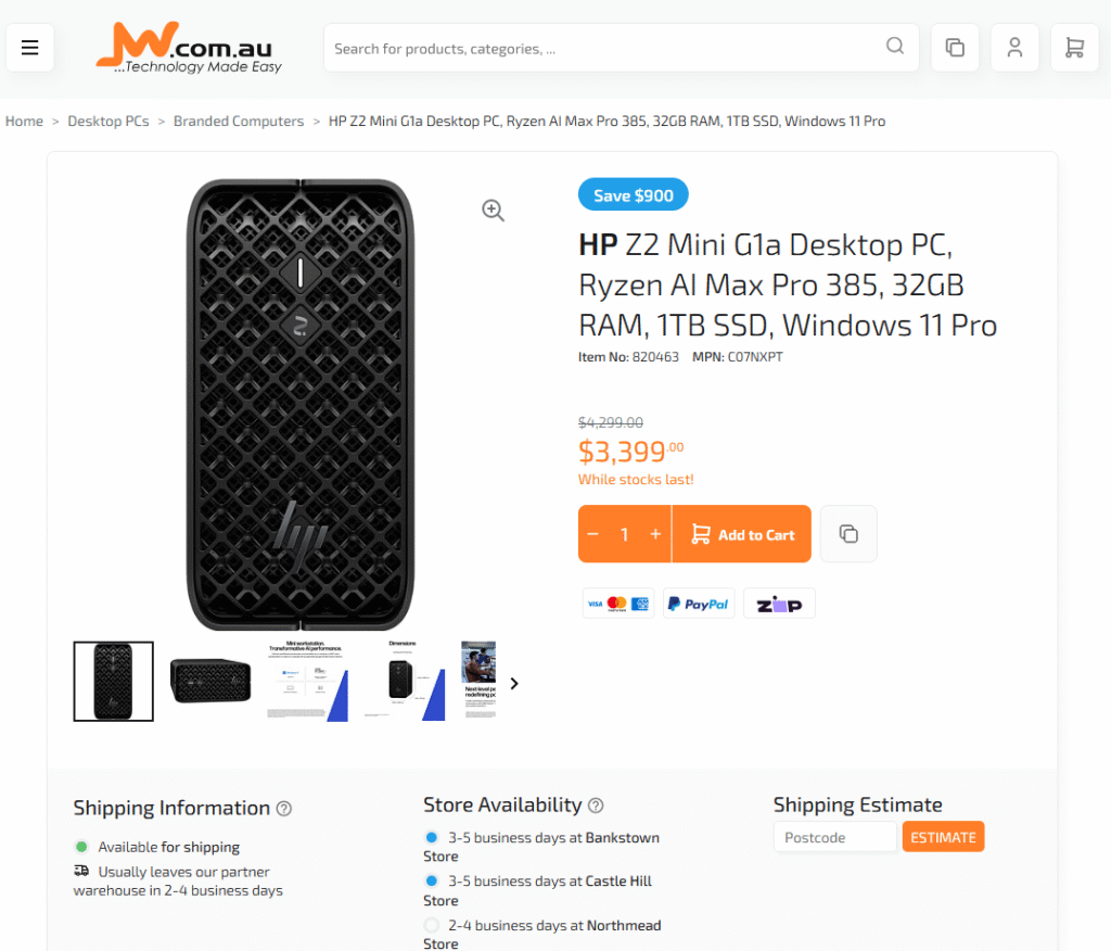
That was around AU$2400 and I still had budget for better CPU or better GPU. Don’t get me wrong, I am not complaining about Framework desktop being overprice, because it isn’t. Of course, they have to make profit out of low volume product and that price point is quite good actually. Compare to HP Z2 Mini G1a for AU$3400 with lower specs, it is actually plenty cheap
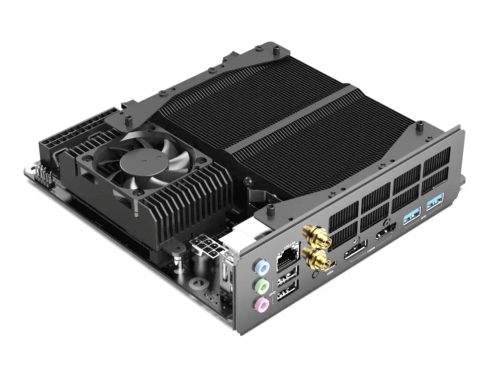
I could go with BD790i X3D with Zen 4 7945HX-3D (about 5-10% processing power lower from Zen 5 395+ AI Max), and still have ITX form factor (same as framework motherboard, but without the grunt of iGPU).
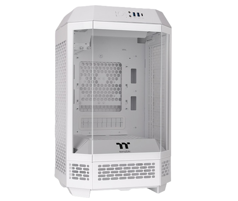
The size is 170x170mm, very compact and small. But I have to pair it with a discrete GPU as well as SFF/SFX PSU which is not that small to fit into tiny case. I did have a thought about some fancy cases like Thermaltake tower 250, though it is huge considering support only ITX motherboard
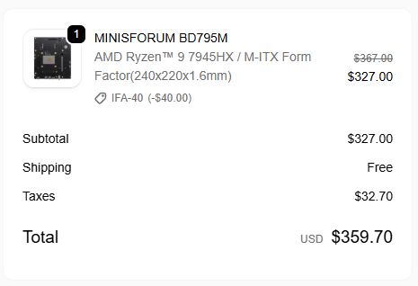
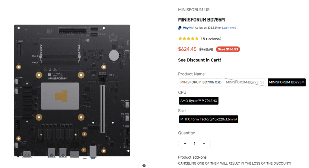
But then stepped down a notch, choosing mobile chip 7945HX coming with BD795M. I was lucky to get the low price before it was jacked up by tariff or whatever. And 3 weeks later, this is the new price almost as twice as much.
US$360 = AU$546 and US$624 = AU$946 (exchange rate at the time of this post)
Compare to R7 9700X, R9 7945HX is about 15% less to 9700X in single core task but overpower by 40% in multi-core task. This is quite easy to understand as it is 16 core Zen4 vs 8 core Zen5. This actually perfect for me. I don’t play game much so that single core task is less important for me, but I’d like to open multiple chrome tabs, like 20-30 tabs at a time.
I saved about AU$350 out of AU$900 for similar performance.
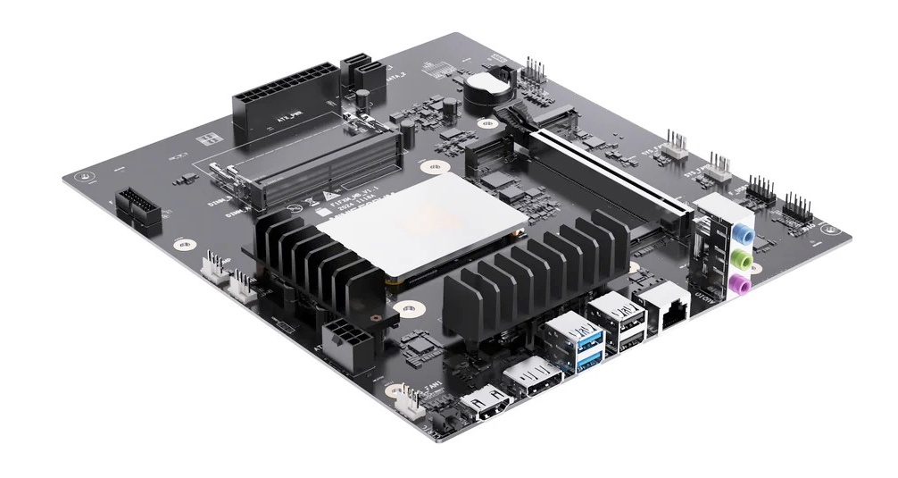
Yeah, this is mATX board and it takes SODIMM instead of DIMM. It’s common to use SODIMM in constrain space of small form factor PC, like Dell optiplex micro series, but there are plenty of board space here. It would be better to use DIMM ram instead. There are much more options to buy DDR5 desktop ram, but less options for DDR5 laptop ram.
I feel funny about this board: AMD CPU but employs Intel 1700 socket heatsink fan. And of course, this spells trouble for me. More to it later.
So, the TDP of CPU is configurable in BIOS for 75w or 55w, quite power hungry for a mobile CPU (a highend one actually).
Assembly this PC is very much the same as normal desktop PC
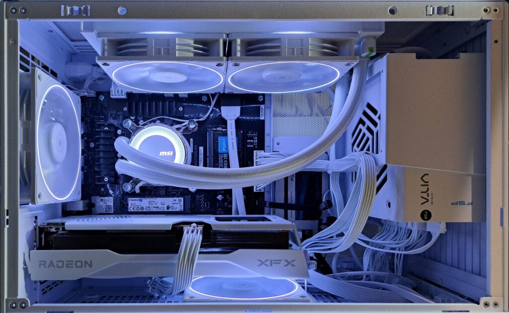
Except when it isn’t. This is the specs:
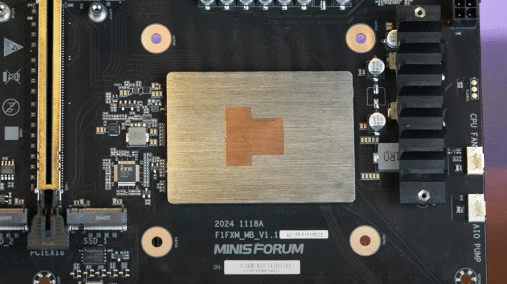
BD795M motherboard with mobile Ryzen 9 7945HX (soldered)
2×32 DDR5 SODIMM Crucial 5600MT
2TB Kingston NVMe
Old wifi module salvaged from broken laptop
XFX 9060XT 16GB
MSI MAG E240 AIO watercooler
3x Thermalright 120 fan
Lian Li A3 mATX case
FSP Vita GM 750W (modular)
The maximum power consumption is roughly 300w (CPU 75w + GPU 160w + FANS + SSD + RAM….). I was aiming for 500w or 550w PSU, say, 40% more for headroom. But for modular PSU, there is nothing below 750w, kinda sad.
Overall, the process is quite straight forward:
sit ram, nvme ssd, wifi card on the board, install CPU bracket / backplate
put the board in the case
install GPU
plug in power cables
do cable management a bit
install radiator
install CPU cooler block/pump
install fans
boot up and install windows
do final cable management
Nothing worth to note down really
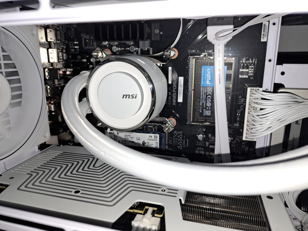
And here comes the trouble with AIO cooler
It went smoothly but then I booted into windows the CPU temp was 95°C. I was kinda panic, as leaving CPU burning hot like this is not good. Fortunately, this board already has a beefy heatspreader, to prevent the CPU from release the magic smoke.
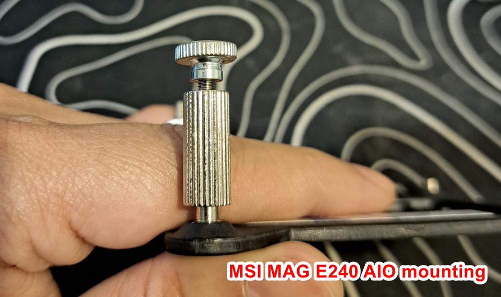
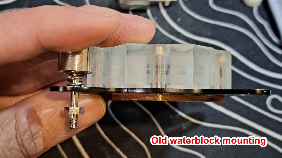
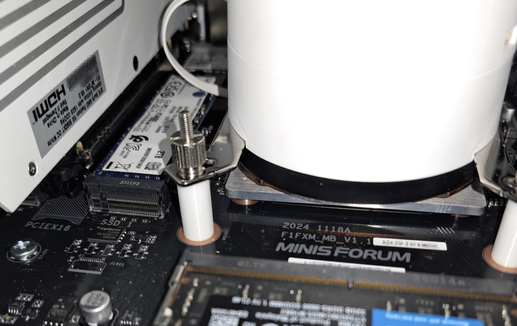
Here is the problem: this AIO bracket/mount thing doesn’t have springs for compression like other waterblock mounting, but a fix-length spacer or standoff.
The idea is good, as fix-height standoff like that won’t bend the motherboard if you tighten the nut too hard. I am sure it’d work wonderfully for Intel CPU.
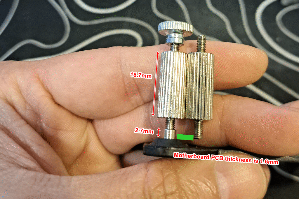
But… this isn’t genuine intel 1700 socket, so the height from the board to the top of the IHS isn’t the same. And that causes thermal throttling as the waterblock never touches the IHS of this CPU. When I removed the waterblock (also pump), the thermal paste, which applied in X pattern, was barely squashed down and still had the same X shape. Bummer! By judging the evidence of thermal paste, there would be about 1-2mm gap. I didn’t take picture of it so you have to take my word for it.
Futhermore, the standoff doesn’t sit flat on the motherboard. The back plate was rattling around when I was installing the motherboard inside the case. I guess that is why they have 2 strips of double side tape on the backplate to keep it in place not rattling around.
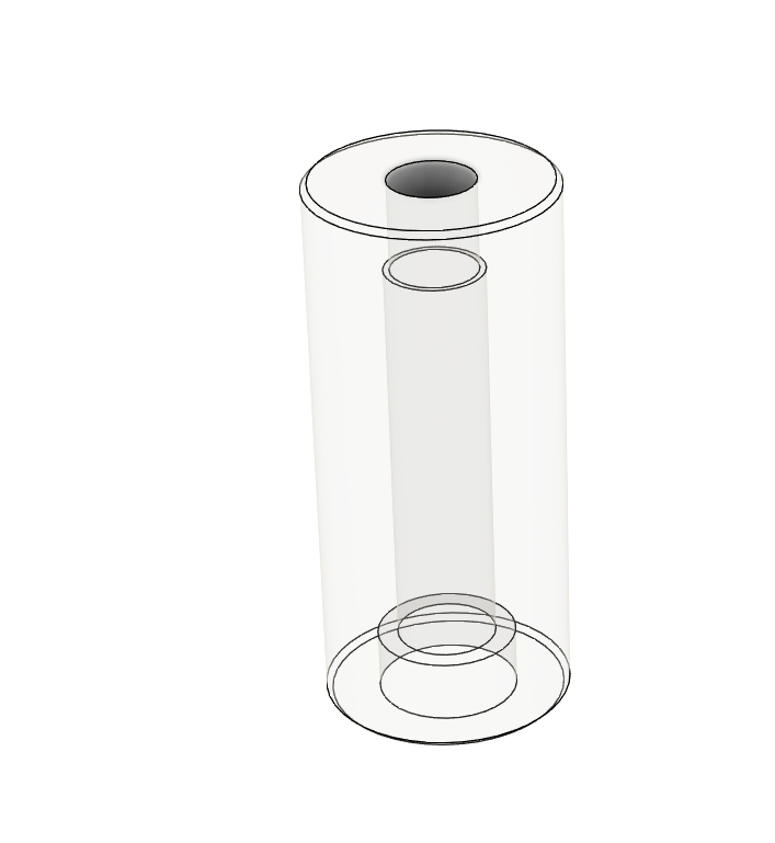
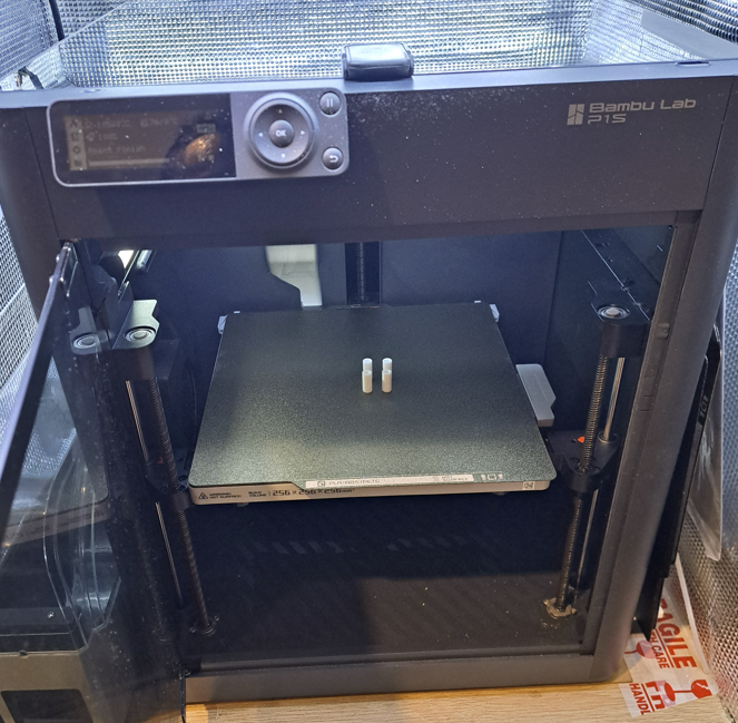
The solution is easy, 3D print a standoff 18mm height to replace original standoff. That is to reduce about 1.8mm off the height of original standoff of the cooler.
These 3D printed standoffs combine with M3 screws 40mm long is perfect setup for me. I print this in PC. It has to be impact resistant as well as heat resistance. ABS or ASA may work but not PA (including PA-CF). Because PA does creep too much under compression, that’d potentially undo the nut holding it down.
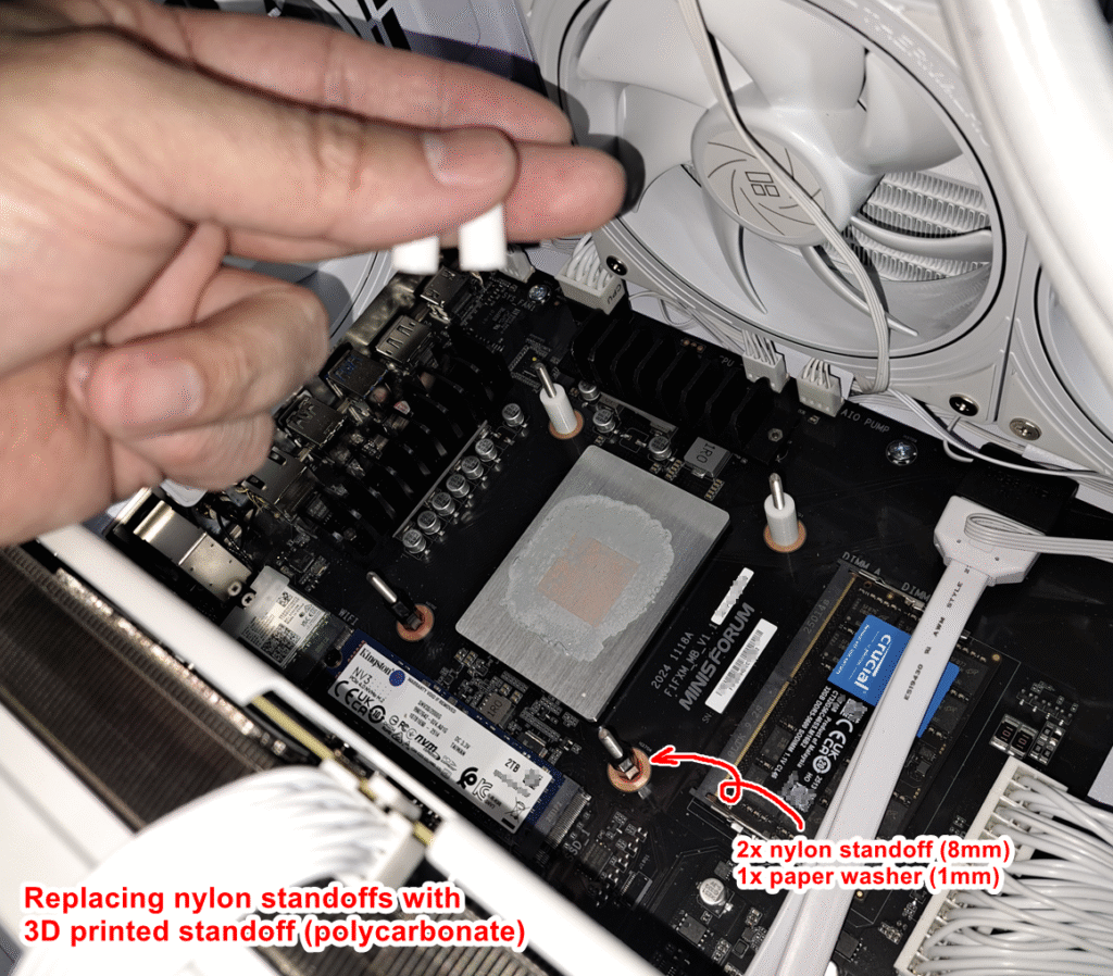
Well, if you don’t have a 3D printer or nuts or screws like what I have, then sucks for you. I really can’t imagine how you can deal this situation, probably return the MSI AIO cooler and try something else. I happen to have quite a collection of M3 screws and nylon standoffs for electronics and this designing and solving problem is kind of my work actually.
You probably get away with 2x 8mm nylon standoff (PA6) + 2x washer + 40mm long M3 screw for each corner. These injection molded nylon part does not creep under compression unlike 3D printed PA6 part. However, it feels like fixing stuff with sticky tape, so that is why the 3D printed standoff instead.
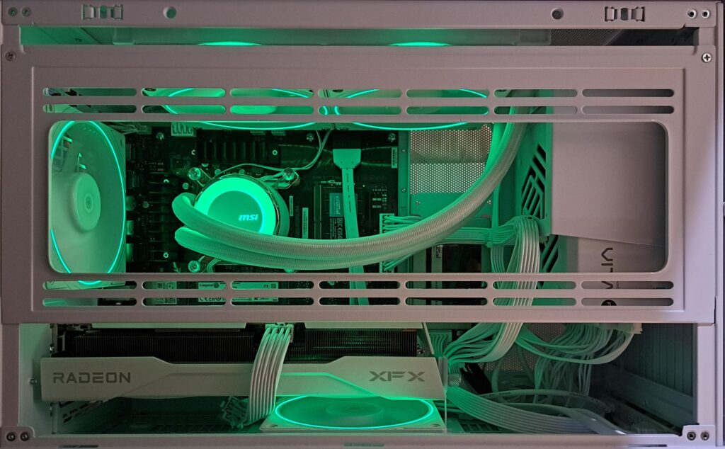
Yeah, I replace MSI fans to Thermalright TL-S12W since I bought 6 of them for matching style and lighting. Unfortunately, BD795M doesn’t have ARGB controller, which is quite odd. Nowadays all motherboards should have ARGB controller onboard already. I did have a thought to build the controller using arduino plaform since it is just Addressable RGB LED and mostly arduino library would run just fine, but meh! Just buy a off-the-shelf cheap controller and be done with it.
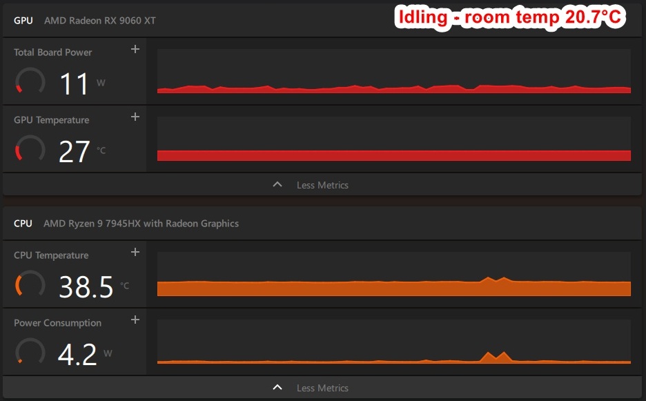
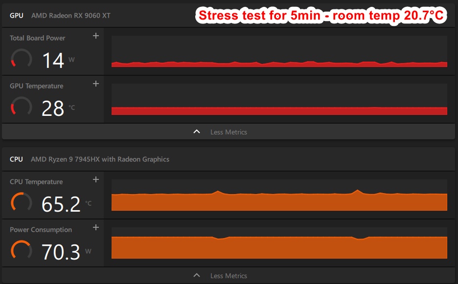
The system runs very well and cool, and very quiet
The CPU is cool, as it is watercooled of course. Anyhow, this thanks to great performance of MSI MAG CORELIQUID E240
TDP of 7945HX is set 75w in bios, which is slightly higher than 65w of most AMD desktop chips but still no problem for MSI MAG E240.
I really don’t care much about benchmarking number. It is like, your car can do 350 KMH but speed limit here in Australia is 110 KMH for motorways and 50 KMH for local streets. I agree you need some number to tell the performance differences between systems, but I’m just too lazy to install those benchmarking software (haha). A youtuber claims this BD7950M is quite close to Cinebench R23 benchmark of 7950X desktop variant, which is 170w TDP and costs twice as much.
Compare to my old system, this is much aesthetically pleasing
Possibly improvement CPU cooler mounting
For now, the CPU cooler mounting is exactly the same, only the height of standoffs are different. And yes there is a tiny chance of the nut will loosen itself because of thermal cycling. To fully eleminate it, I have a plan to use blinded M3 nuts + springs to have constant pressure, which of course would be better. The blinded nuts still stop it from going down too far. Combine with the same spring at 4 corners, then you’d have same pressure on four corners.
I saw some dude chipped off a corner of the die of AMD Athlon K7 (Thoroughbred or Barton, I forgot) while installing homemade watercooler, around 2003 or so. Yeah, the good old days.
And this would complete the build. But for now it is well enough!
————————
If you have the exact same system and want to print the standoff, here is the fusion archive file:
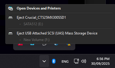
After a week of daily use, I found a small problem that I couldn’t solve: The SATA drive pops in the “safe remove menu” of windows and I eject it by mistake. Actually I was quite careful before I click but I wanted to try and see if it is possible to eject the SATA disk like a USB drive, it did actually eject the SATA drive. So, I had to open the side panel of the case and reconnect the sata cable and *voila* the drive enumerates itself back in the system.
I tried to look for an option to disable hot-swap feature but failed. I didn’t have high hope anyhow as I knew the BIOS is just bare metal before I bought it.
Support from MINISFORUM told me that this motherboard does not support SATA hot-swapping (as expected) and thus there is no option to disable it in the BIOS.
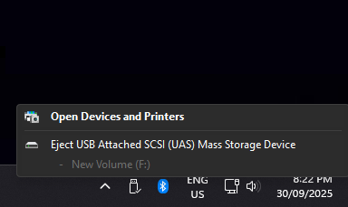
I found a registry hack to hide these SATA drives from Eject menu
TreatAsInternalPort.Reg
Windows Registry Editor Version 5.00[HKEY_LOCAL_MACHINE\SYSTEM\CurrentControlSet\Services\storahci\Parameters\Device]"TreatAsInternalPort"="01"
That will hide SATA port 0 and SATA port 1 from Eject menu
You just save as reg file or open regedit and create a string TreatAsInternalPort with content “01”, DWORD 32 or DWORD 64 type also works but the content is different as byte string {‘0’, ‘1’} convert to DWORD32 = {0x30, 00, 00, 00, 0x31, 00, 00, 00}. You know, DWORD32 = 4 bytes for a single character while byte string = 1 byte for each character.
If you are old like me, like 30-40 years old. You would know the annoying office assistant Clippy coming with Office 2000. Yep, that was 20-24 years ago!
Most of us would immediately turn off clippy the moment he showed up. Back in the day, Clippy was nosy but he just wanted to help you. He didn’t collect your data secrectly and sell it for profit.
But now every big corps collect your data and use that to shove very targeted ads on your face. To name a few: FB, Google, Microsoft…
Yes, those big coprs actually are spying on you. It’s not a conspiracy like government wants to spy on you or control your mind. It’s already happened and you voluntarily give away your data! It’s your frigging phone!
Have you wondered how FB making profit if they don’t have any product to sell? You are the product. You are farmed by FB, you are watching personal targeted ads on FB. Yes, FB is cashing out with ads views by you!
Watch this video
If you don’t like big corps spying on your activities and slap targeted ads on your face, join Clippy movement!
But we all have to get together. And the first step is making it public that we know what’s going on. That starts with a clippy, on YouTube. If you’re with me, I ask that you change your profile picture to a clippy.
TLDR; I upgrade my soldering station. Design and print standalone stand for the handle. Include some ranting and story behind it.
My first homemade soldering station was made 8 years, more or less. It still works just fine. During the years, I’ve made a few more giving to friends. They haven’t complained, yet! (haha).
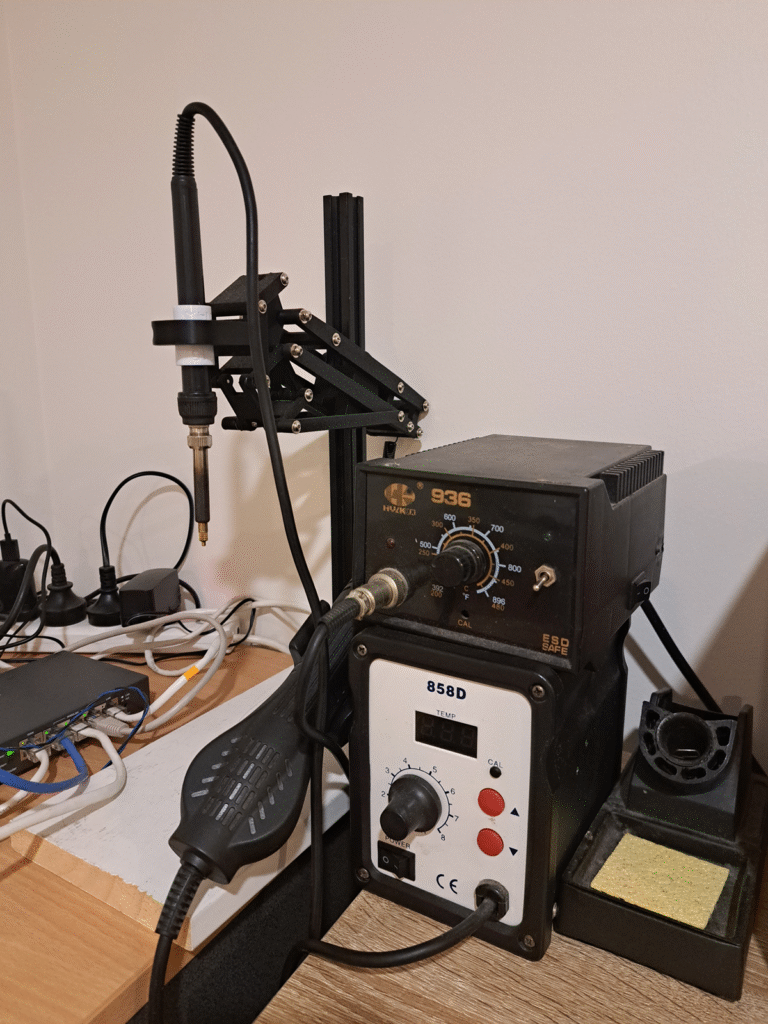
My first soldering station was HYLKKO 936, a Yihua 936 clone and chinesium copy of Hakko FX888D. As you might have guessed it, it wasn’t that bad, certainly an upgrade from cheap soldering iron that has a no temperature control circuitry. It took quite sometime for the iron tip (900M series tip) to get up to temperature. There was no sleep function, pretty much the tip stay hot up to target temperature as long as it powered.
The problem is, I forgot to turn it off a dozen times. Yes, I left the solder iron 300°C hot for half a day until I turned off the light, going to bed. And just at that moment I saw the only frigging LED of the solder station was blinking on for a brief moment… That only red LED turns on when the temp rising up but off when reaching the correct temp. If it is idling at target temperature, that LED only turns for half a second then off for 10-20 seconds. The good news was it didn’t pump power to the iron tip constantly, but only top it up to keep the temp at target. But still, leaving something burning hot unattended was really really bad idea.
There are two scenarios here:
They forgot to put an extra LED or on the face plate to help user like me to turn it off, or just want shave off $0.001 cost of an LED and a resistor.
They don’t care about user experience, the iron does get hot and that is enough, wrap it and sell it
I tend to think the latter is the case here. This is what China is well-known of, the Chabuduo mindset, google it.
At some point, I had to make a simple buzzer that beeps every 5 minutes to remind me to turn it off. Now it is permanently a heat set press jig for installing threaded brass insert. It did serve its job to help me build my own soldering station though.
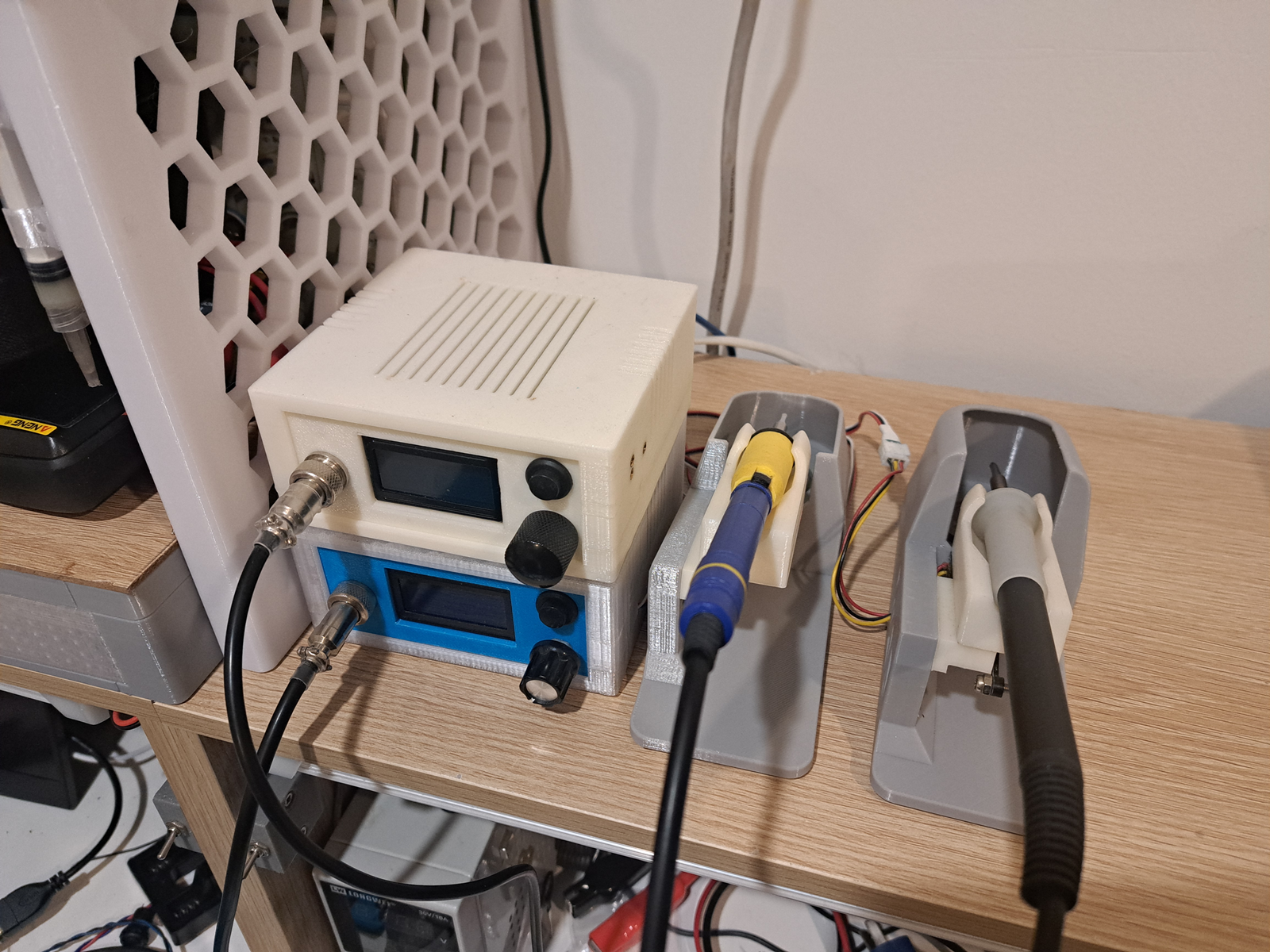
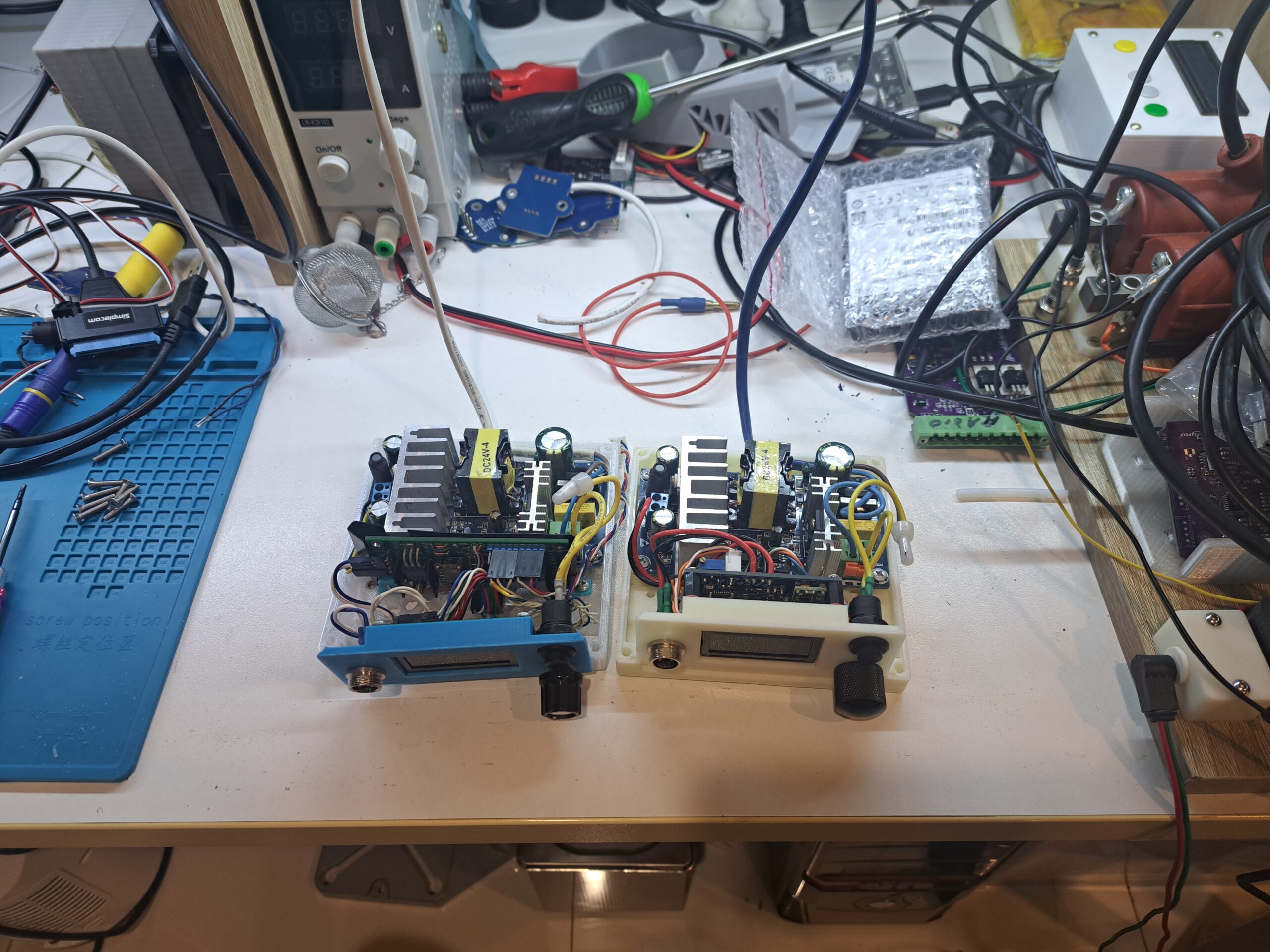
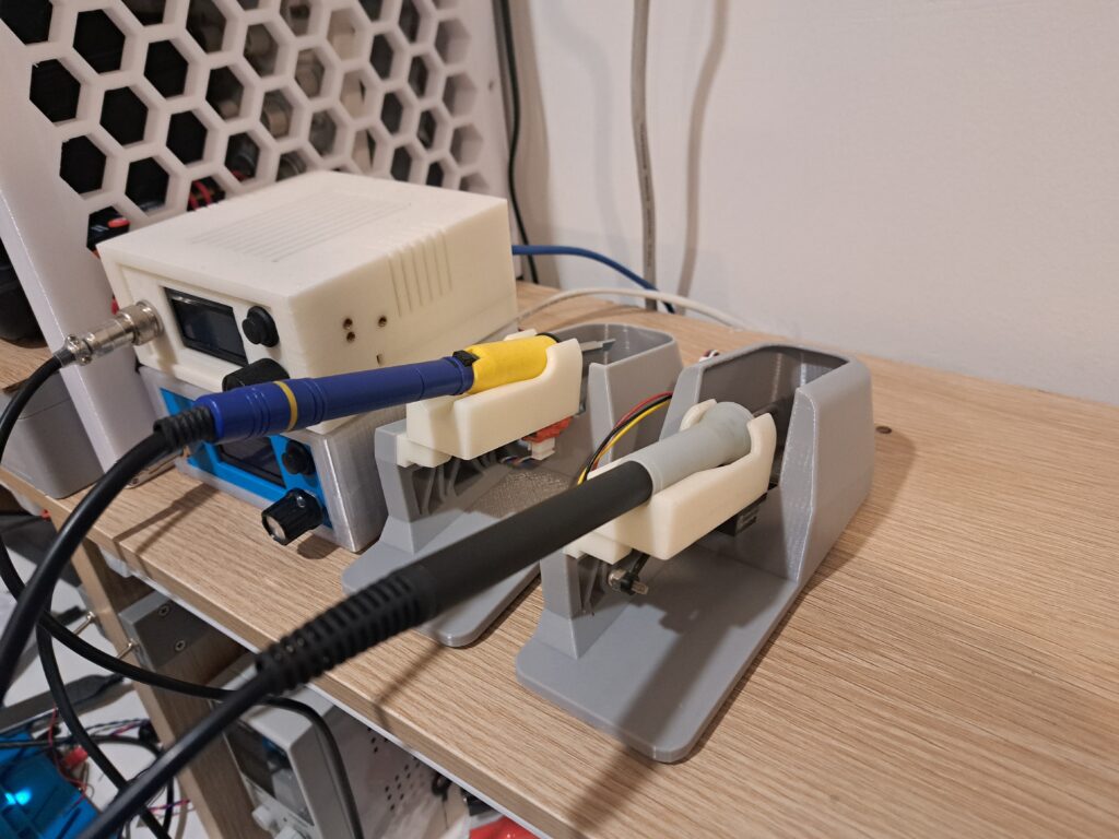
Recently, I moved house, set up new home-lab and I pretty much rearranged everything. I have 2 active soldering stations + hot air station now, exclude that weird heat set press jig.
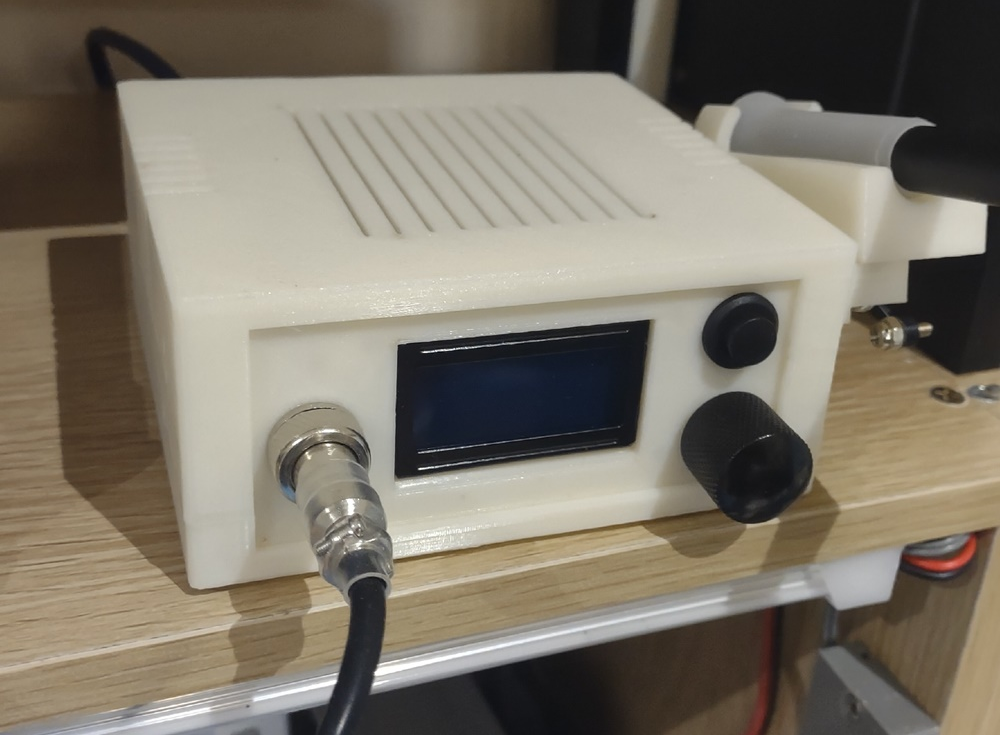
Before that, the soldering iron stand was bolted to the side of the case as one piece, very convenience, having them easy to pack up to go. The case was ABS print, still strong after years of service.
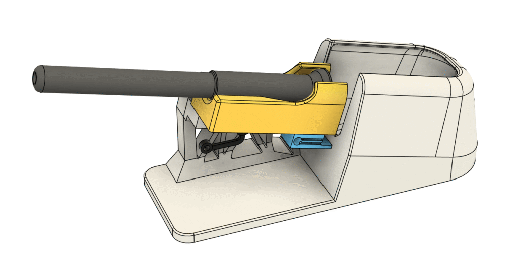
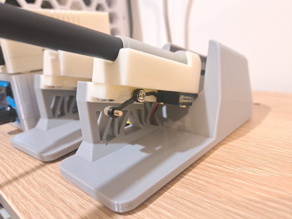
Imagine when I stack 2 of them on top of each other. Yeah, kind of awkward with the iron stand on the side. Thus, I need a standalone stand for the handle.
What a big deal? just go buy a stand from aliexpress or go search Makerworld, printable and print one? Yeah, nah.
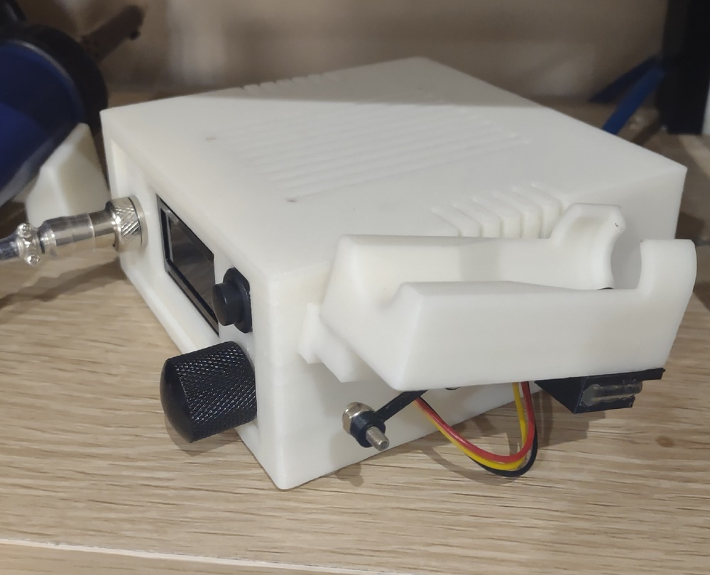
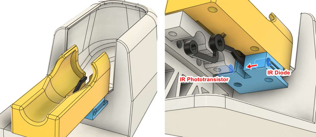
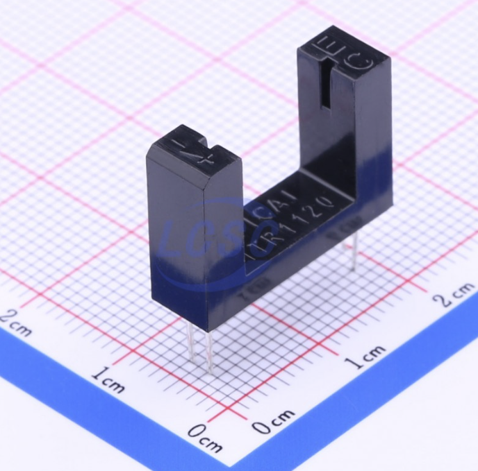
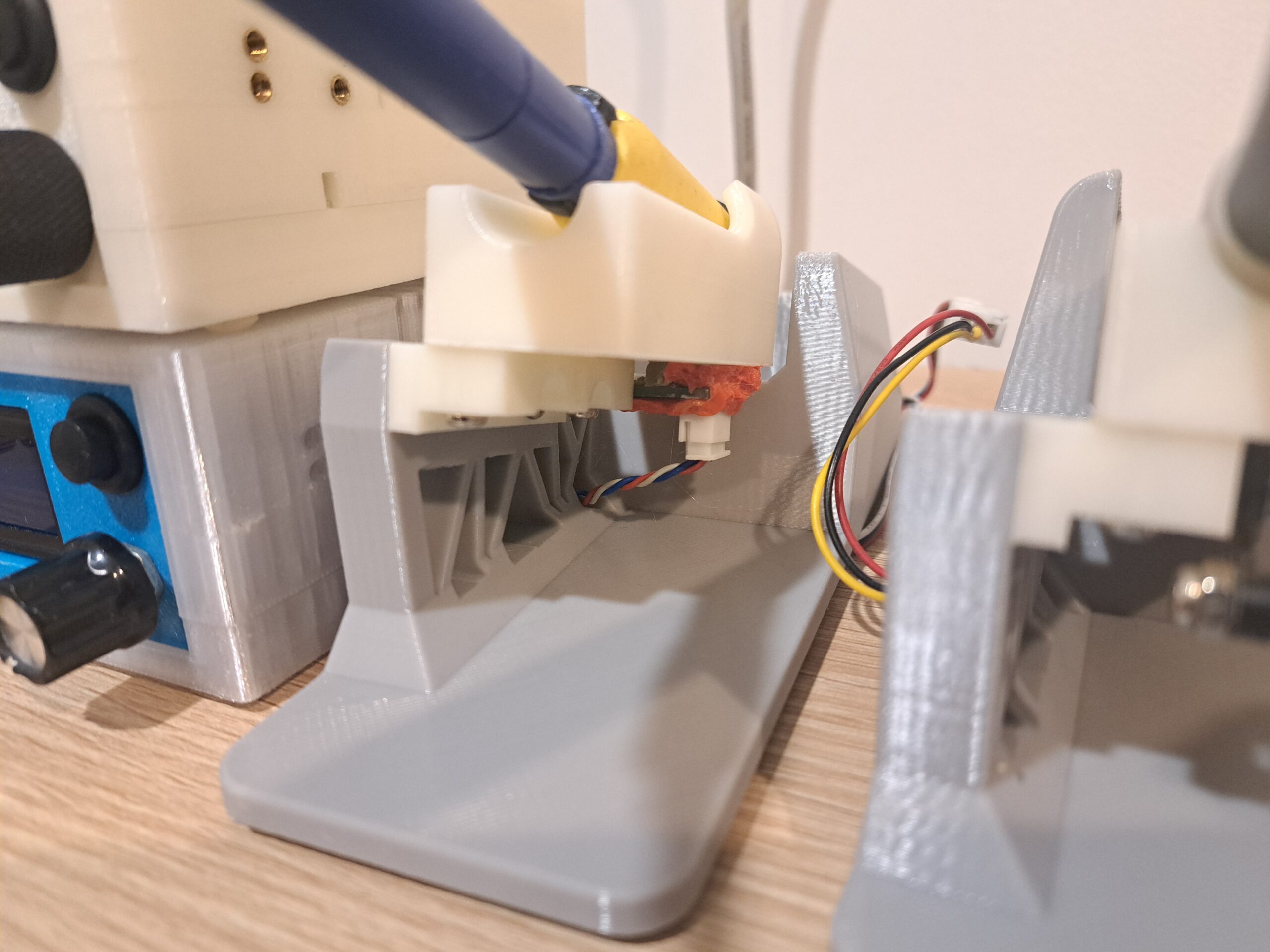
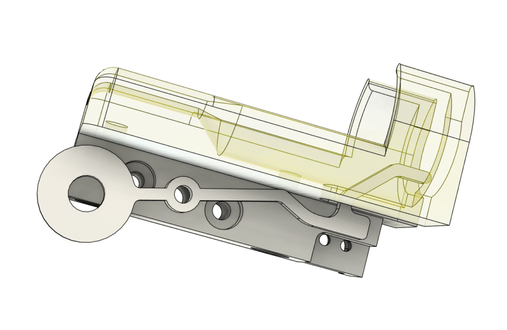
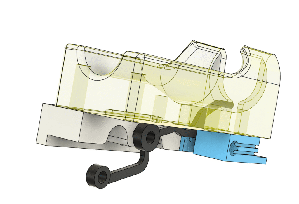
I have a custom optical sensor (photointerrupter) to detect if the handle is docking, so it will trigger sleep function of the station. The sleep function will keep the tip around 200°C for 5 minutes then turn off the heater completely afterward. This is just for safegarding for user who forgets to turn off their stuffs like me! So, even the case I forgot to turn soldering station off for days, it’d still be safe, the iron would be room temperature cold.
When the handle is put in the stand, the black lever is pushed down and blocks the IR beam –> hence it called photointerrupter. Pretty much the same as off-the-shelf part, but I don’t have to make a small PCB to hold it. Making PCB and design a way to mount that photointerrupter was kind too much to do. So I rolled with my custom design, it was easier, I don’t have to go back and forth between fusion and kicad.
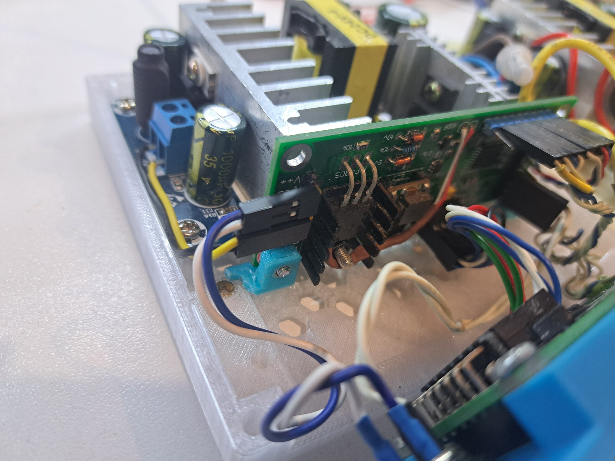
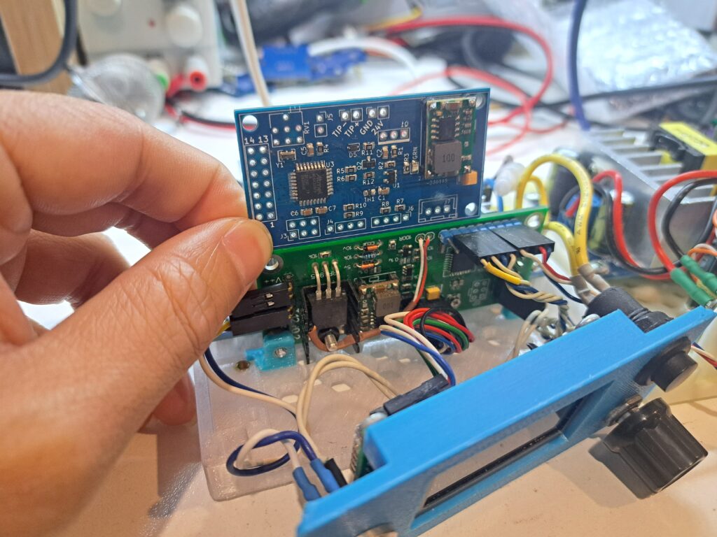
Some pictures compare the first PCB vs the second iteration
The second iteration has some differences in pin configuration as well as minor change in circuitry:
Different pins for driving the LCD0802
Employ AMS1117 as post filtering, improve temperature reading. First iteration use mini360 directly without post filtering
Use a simple LED (forward bias) instead of zenner diode (reverse bias) to clamp voltage at input of LMV321
Use 0805 thermistor just to measure temperature inside the case, no need to measure temperature at the MOSFET
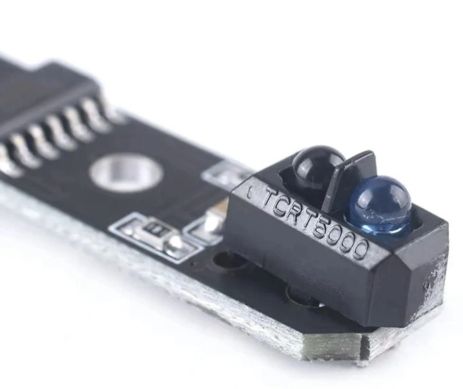
Differences in docking sensors
The left one used TCRT5000 in a module for line tracking sensor, as my first experiment. It was basically 2 LEDs, IR diode and IR phototransistor put inside a small plastic case. It works by detecting reflecting IR beam from a white-ish surface for a HIGH level output, while dark surface reflect much less IR beam for a LOW level output.
But of course it only works with bright color handle! Yeah nah ~_~.
Then I did some experiments with this reflection method. It never worked correctly. Then I changed the sensor design to interrupting instead of reflecting and it worked much more reliable.
If you read to this point, congratulation! You are just bored and have nothing to do 😀
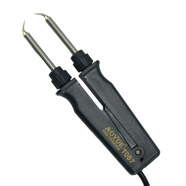
And you probably wonder why would I want 2 soldering stations? The answer is: desodering SMD stuffs using 2 soldering irons, like 0805 or similar size. I just need to heat up 2 ends of the part and pick it up just like a tweezer.
Hotair station is handy for SMD, but sometime this tweezer trick is a lot faster and safer especially working with PCB that has plastic connector such as JST XH. You simply don’t want to deform the connector, yeah?
So yeah, after 8 years the very first soldering station I made still runs just fine. The cost of each station is about AU$60. Compare to Hakko FX951 ~AU$400 of the same function, it’s not bad at all.
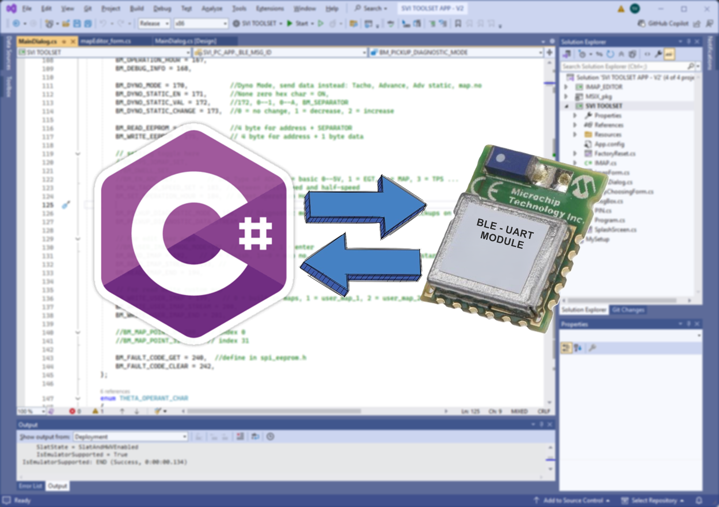
This post is about how to write a C# winform app to connect to your project using BLE module. This post is from point of view of an electronic engineer instead of software engineer and just focus on the BLE communication programming part only, especially for those UART transparent BLE modules, like RN4871. There is no complete sample in this post but just some hints and code snippet here and there to help with programming.
Introduction
Imagine, you write a windows app and you need to collect data from your microcontroller project, then pretty much you need to find a way to link them together, yeah? There are obvious choices:
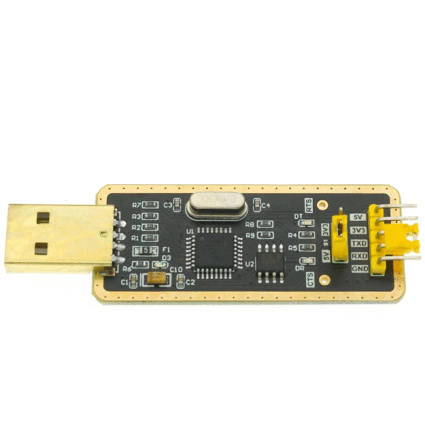
USB to UART dongle and wire it up directly to UART port on your microcontroller
Implement wifi and IoT (internet of thing) software stack on your project and communicate with your host app via TCP-IP or so, like ESP8266 or ESP32
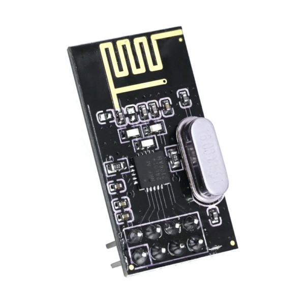
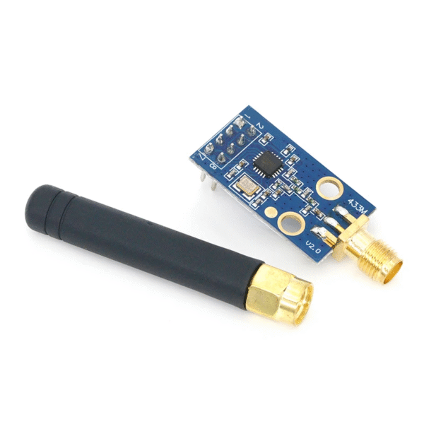
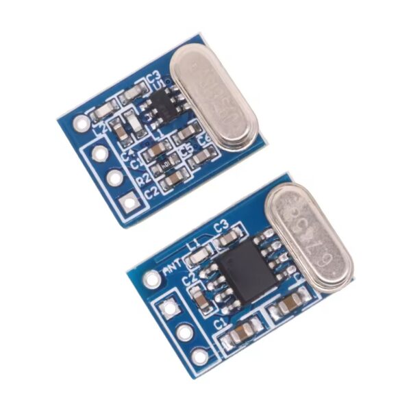
Use some transceiver modules and convert UART into RF, like RF24L01, CC1101, or just simply bit-bang data over a pair of 315 MHz transceiver modules
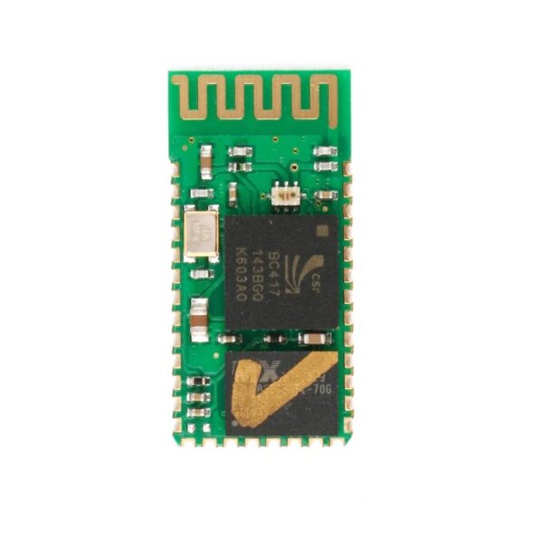
Use Bluetooth (known as BT classic) over virtual COM port, by using some module like HC-05
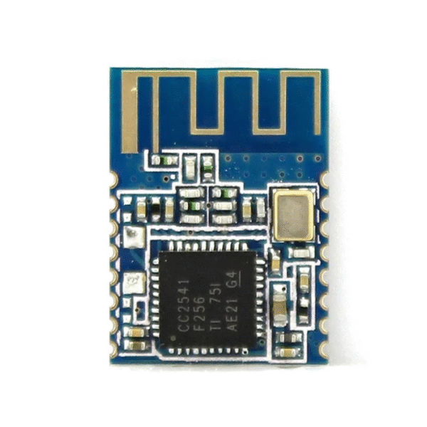
Or just use Bluetooth LE (BLE or bluetooth low energy)
Below is the pictures that I stole from the internet. And yes, I have tried them all.
If we wound back to 20-30 years ago, the obvious choice is BT classic and virtual COM port for a commercial product. Unless your project needs to dump a huge chunk of data without any loss, then you should choose TCP-IP over ethernet cable or wifi instead. But now, BLE is so popular these days, why not choosing BLE instead, yeah?
Before I wrote SVI-Toolset app, I really struggled with researching BLE communication programming on windows PC: there was almost no windows app, nor there was a solid sample code for windows PC to connect to a BLE module. I am talking about off-the-shelf module like RN4871, CC2541… The only really working sample I could find was BLE console. It was around Feb 2023 when I started experiment with BLE and untill today, Aug 2025, I still couldn’t find a working sample from M$.
Of course, there are some paid framework to work with BLE, which framework also compatible across muliple platforms, like Windows, MacOS, Linux… But for some small fry like me, it’s not possible to invest in a large sum of money and time for that.
Okay, enough ranting, let’s dig into the good stuff!
Prepare visual studio project
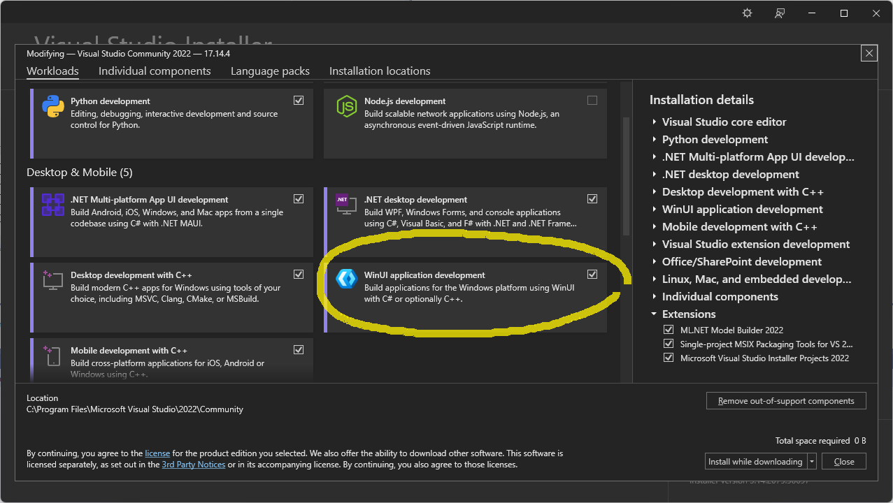
You might need newest visual studio. At this time of writing, VS Community 2022 is free. Make sure you install WinUI application development (or windows ux for older visual studio).
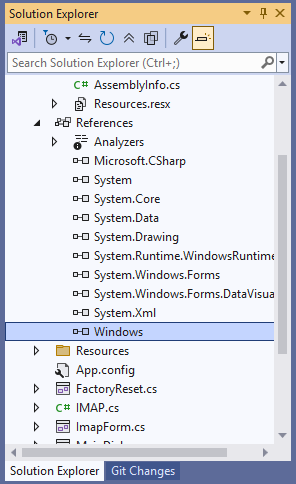
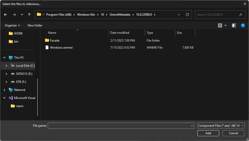
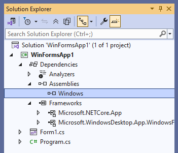
Just start a new winform project as usual, nothing special here. The trick is to add reference to windows ux library that provides headers for Bluetooth or Bluetooth Low Energy. Go to project list panel, add reference and browse to the header file:
If you can’t find this folder, then just download and install Windows SDK or choose a newer version that you have. I still use old version just fine, which version was for windows 10, instead of using newest version 10.0.26100
You actually can use VS2013 and install Windows SDK for the same header instead of using VS2022.
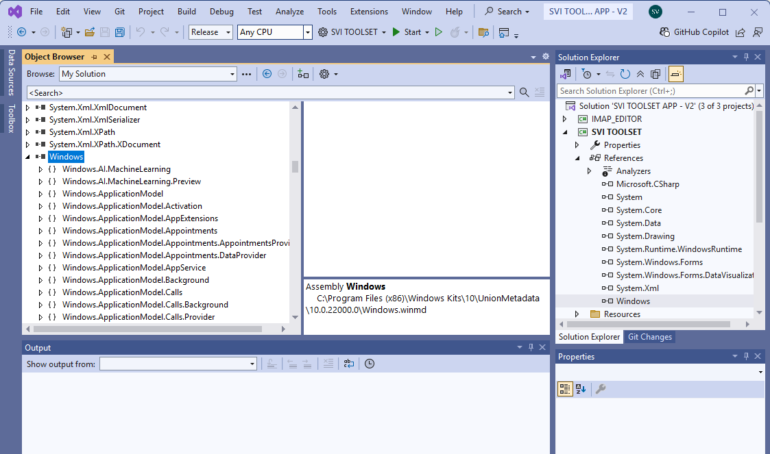
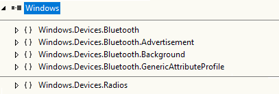
If you double-click on the the assembly name you will see all of the supported classes that this header provides. Among tons of classes this windows ux supports, we are interested in:
So, just add a winform dialog maybe, and a couple of labels, buttons… Then <view code> of your “form1.cs” and add those classes to your code.
Sorry if I am mixing terms from C++ and C#, I code embedded C more often than winform C#.
I’ll spare you the boring detail about BLE, GATT profile, GATT service… whatever. You can read it here https://www.bluetooth.com/. However, I am sure after you read/watch a sh!t load of those documents and videos about BLE, still you couldn’t write program to talk to a BLE module. But of course I have to include a tiny bit of info about this, just enough for you to write code.
Okay, before I go on, I advice you to forget everything you know about BT classic and all definition of server/client or host/client you understand so far. I could have sworn those BLE definitions were made to brainf~ck with us. Just try not to compare BLE with everything you know, okay?
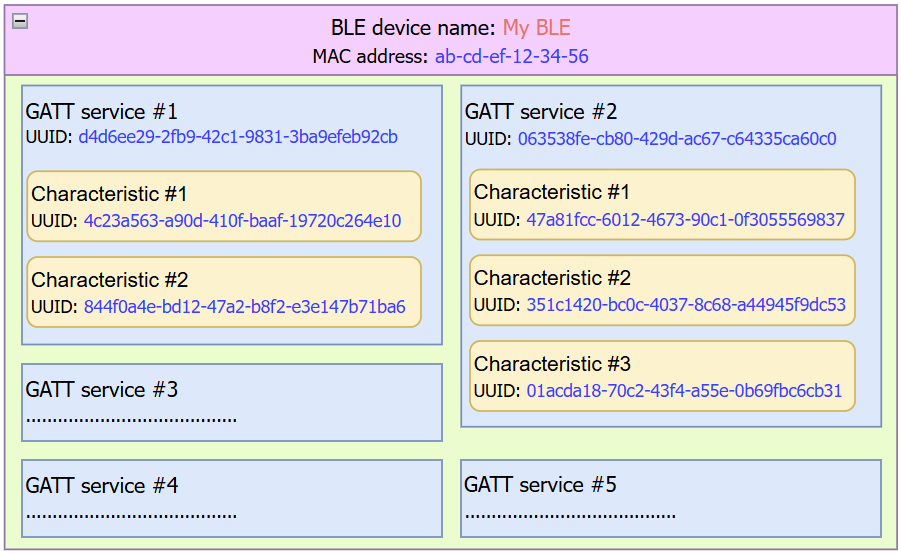
Every communication should be 2-way, yeah? Unless your project is about just sending out data, like temperature sensor or an SOS beacon. So that you need send and receive which is 2-way communication between 2 devices. BLE stuff doesn’t provide a direct definition of send and receive like a conventional communication like UART or SPI. but for BLE, you have multiple GATT services (or GATT profiles) on a single device, but most of the time you have only 1 or 2 services. Each service may be for different purposes.
You should only use your BLE device as BLE server and run the GATT services that your PC app can send request to. Below is what a BLE device should be like
So each BLE differenciates to another by their name and their MAC address while GATT services and Characteristics are distinguish by their UUIDs. Those UUIDs above were mocked up, btw. Basically, it is just the same as company tag, division tag, and individual worker tag. You can define your own tags to BLE device as you like. Some of off-the-shelf BLE modules do allow you to change those tags, others don’t.
Each characteristic could have multiple properties: read, write, notify… You don’t have to understand those properties. I can say each characteristic is a basket to hold the message so it can be 2-way or one-way. Normally we set UART-TX on one characteristic and UART-RX on another characteristic to eliminate confusion. Datasheet of the UART transparent BLE module will tell you exactly which characteristic is to send or receive of UART.
Your PC app must manage the BLE devices on its own. It seems more work, but it’s actually better for the user. Think about the old way, user has to find the correct COM port to connect to. It’s more trouble if user plugs in many devices that pop up as COM port, such as Arduino Leonardo, CP2102, CH910F. Arduino Leonardo driver is the most troublesome, as it pops up as different COM port when plugged in different USB port. Additionally, most users are not tech savvy who can open device manager to read the COM port number.
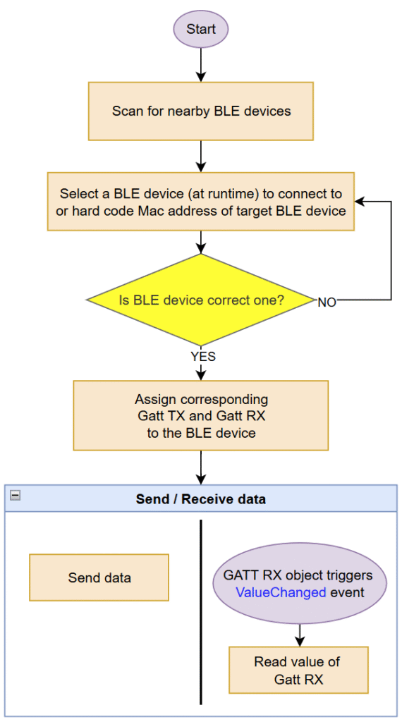
To simplify, You need to
Scan for nearby BLE
Select the correct BLE – store it’s Mac address for future use
Assign that BLE device to bleObj
Assign correct Gatt Service to gattSer
Assign correct Gatt Characteristics to corresponding gattRXand gattTX
Add event listener that monitors ValueChanged of gattRX
Use gattRXobject to receive data
Use gattTX object to send data
Easy peasy, lemon squezzy!
Scan for BLE devices
There are two class you can use for scanning nearby BLE devices: BluetoothLEAdvertisementWatcher and DeviceWatcher
Ok, so BLE is totally completely different beast to BT classic. You DO NOT go to Bluetooth and devices to add a new BLE device. In fact, you don’t have to pair with BLE device using system. This is true for Windows and Android. I don’t know about iOS or linux though.
The ble “connected” status is just a virtual concept, as ble device only wake up, send data, then go back to sleep. Mostly. There is no need for pair or sync. Of course, BLE is not for transmitting data securely, so keep in mind that you should obscure your data before sending over BLE, by encoding or encrypting the payload.
You have to manage BLE device inside your code: scan, connect and disconnect! Yup, disconnect just makes killing the “virtual link” between PC app and BLE device quicker. There is a timeout before the BLE module decides to accept “new link” and broadcast its advertisement again, for RN4871 this is about 5s.
Okay, both BluetoothLEAdvertisementWatcher and DeviceWatcher can be used for scanning BLE beacons to detect nearby BLE devices, they are practically doing the same thing.
The only different is BluetoothLEAdvertisementWatcher only listen for BLE beacon or BLE advertisement messages. This can be super useful to filter out non BLE device nearby. While DeviceWatcher will monitor all nearby devices.
Using BluetoothLEAdvertisementWatcher is super easy
C#
// short versionBluetoothLEAdvertisementWatcherble_watcher;ble_watcher = newBluetoothLEAdvertisementWatcher();ble_watcher.Received += (BluetoothLEAdvertisementWatchersender, BluetoothLEAdvertisementReceivedEventArgsargs) => { /* add new device to the list here */ };// run the watcher when you need to scan nearby ble devicesble_watcher.Start();
Longer version of
C#
// a class to hold string data, similar to struct of C++classMy_BLE_Device {publicstringname;publiculongaddress;publicshortRSSI;publicMy_BLE_Device(stringdevice_name, ulongdevice_address, shortmy_RSSI){name = device_name;address = device_address;RSSI = my_RSSI; }}List<My_BLE_Device> _ble_dev_list = newList<My_BLE_Device>();voidscan() {BluetoothLEAdvertisementWatcherble_watcher;ble_watcher = newBluetoothLEAdvertisementWatcher();ble_watcher.Received += BLE_watcher_receive; // run the watcher when you need to scan nearby ble devicesble_watcher.Start();}// callback function when a new BLE device pops up in the scannerprivatevoidBLE_watcher_receive(BluetoothLEAdvertisementWatchersender, BluetoothLEAdvertisementReceivedEventArgsargs) {if (args.Advertisement.LocalName.Contains("SV") || args.Advertisement.LocalName.Contains("BLE")) { // found devicevarfound_ble_dev = newMy_BLE_Device(args.Advertisement.LocalName, args.BluetoothAddress, args.RawSignalStrengthInDBm); // check in our list if not existif (_ble_dev_list.Count == 0 || !_ble_dev_list.Exists(x => x.address.Equals(found_ble_dev.address))) {_ble_dev_list.Add(found_ble_dev); } }}
Just have to add event listenner to run a callback function when receive an advertisement beacon. You get RSSI (received signal strength indicator) coming along with ble advertisement beacon.
As sample code above, I only choose to add ble devices which name contains “SV” or “BLE”.
In the other hand, using DeviceWatcher is a little bit of dark magic involved
Below is some code I took from BLE Console app
C#
List<DeviceInformation> _deviceList = newList<DeviceInformation>();string_aqsAllBLEDevices = "(System.Devices.Aep.ProtocolId:=\"{bb7bb05e-5972-42b5-94fc-76eaa7084d49}\")";string[] _requestedBLEProperties = { "System.Devices.Aep.DeviceAddress", "System.Devices.Aep.Bluetooth.Le.IsConnectable", };deviceWatcher = DeviceInformation.CreateWatcher(_aqsAllBLEDevices, _requestedBLEProperties, DeviceInformationKind.AssociationEndpoint);deviceWatcher.Updated += (_, __) => { }; // add an empty inline function for this event listenerdeviceWatcher.Added += (DeviceWatchersender, DeviceInformationdevInfo) => { if (_deviceList.FirstOrDefault(d => d.Id.Equals(devInfo.Id) || d.Name.Equals(devInfo.Name)) == null) _deviceList.Add(devInfo); };deviceWatcher.Start();
There are a few voodoo stuffs to put into the initial constructor there, alright. You will get more detail about the device this way but you don’t have RSSI information. For my need, RSSI is more important than extra detail about a BLE device.
Just a note: ESP32’s BLE stack does not play nice with BluetoothLEAdvertisementWatcher. Somehow ESP32 doesn’t advertise it’s ble name, it’s just blank! So, I suggest to use both if you are connect to ESP32 to fix this. If you plan to use ESP32 as a transparent UART passthrough for your project, I advise you not to go into this rabbit hole. Although ESP32 allows you to freely program ESP32 to do whatever you want it to do, but the lack of DMA stuffs of arduino framework, make it very difficult to do it correctly.
Connect, Send and Receive data from BLE module
So, you have a list of BLE candidates, you choose one to connect to and then you should check if the BLE device is the correct one.
One way to do that is to match the UUIDs of the target BLE device with the UUIDs from the datasheet. The code blow is to check if the BLE device has the same UUIDs of TX and RX for RN4871 BLE module.
C#
asyncTaskConnect_BLE(ulongdev_address){ // Try assign a BLE device using its address to bleObjbleObj = awaitBluetoothLEDevice.FromBluetoothAddressAsync(dev_address).AsTask().TimeoutAfter(10000); // Go through all of its available servicesvarresult = awaitbleObj.GetGattServicesAsync(BluetoothCacheMode.Uncached);if (result.Status == 0) { // status = 0 = no problemboolfound = false;foreach (GattDeviceServiceserinresult.Services) { //search through services to get our target servicesif (ser.Uuid.ToString().Equals("49535343-fe7d-4ae5-8fa9-9fafd205e455")) { // found our Gatt service for RN4871gattSer = ser;found = true; } }if (!found) { //if not found the correct gatt servicebleObj.Dispose(); //we got squat, so dispose of this objectreturn; } // we have alread found correct characteristic with the same unique idvarresult2 = awaitgattSer.GetCharacteristicsAsync();if (result2.Status == GattCommunicationStatus.Success && result2.Characteristics.Count>1) {gattRX = result2.Characteristics[0]; // first characteristic should be RXgattTX = result2.Characteristics[1]; // second characteristic should be TX // check if UUIDs are matchif (!gattRX.Uuid.ToString().Equals("49535343-1e4d-4bd9-ba61-23c647249616") || !gattTX.Uuid.ToString().Equals("49535343-8841-43f4-a8d4-ecbe34729bb3")) {bleObj.Dispose(); // no match --> disposereturn; } }else {bleObj.Dispose();return; } // looking good, we got a solid connection // Subcribe to value_changed on RX characteristic => callback Characteristic_ValueChanged()varstatus = awaitgattRX.WriteClientCharacteristicConfigurationDescriptorAsync(GattClientCharacteristicConfigurationDescriptorValue.Notify);if (status == GattCommunicationStatus.Success) {gattRX.ValueChanged += Characteristic_ValueChanged;Callback_DeviceConnected(); // run some routine after have a solid link to BLE }return; // Connect successfully } // handle errortb_Stat.AppendText("\r\nTimeout - Connect fail.");}
Once UUIDs are verified, you have a solid target to read and write data to. So just use gattRX object and gattTX object to send and receive data.
To “connect” or establish a “link” to BLE module, you just write something to BLE device and wait for response. Like the sample below, I write a change of configuration and set it to notify on the receiving GATT characteristic.
C#
varstatus = awaitgattRX.WriteClientCharacteristicConfigurationDescriptorAsync(GattClientCharacteristicConfigurationDescriptorValue.Notify);if (status == GattCommunicationStatus.Success){gattRX.ValueChanged += Characteristic_ValueChanged; // monitor if value of this characteristic changedisConnect = true;Callback_DeviceConnected();}
If success, then the app knows that BLE module is ready to reply to request of the app. Again, there is no definition of “connected” concept for BLE, I just make it up for more intuitive usage.
On PC side, you will have send function like this
C#
// global declareGattCharacteristicgattTX;asyncTaskSendData_BLE(byte[] data){if (!isConnect) return;varwriter = newDataWriter();writer.WriteBytes(data); // WriteByte used for simplicityawaitgattTX.WriteValueAsync(writer.DetachBuffer());}// in data preparation functionbyte[] data = newbyte[5];data[0] = (byte)_BLE_MSG_ID.BM_REQUEST_BATTERY_VOLTAGE;data[1] = (byte)'0';data[2] = (byte)'0';data[3] = (byte)_BLE_MSG_ID.BM_SEPARATOR;_ = SendData_BLE(data); // assign an empty holder for this task
So, you write some data to a GATT service, that assosiates with TX line of UART, and magically on the other end of BLE module, it spits out the same data on its UART port.
Receive function is like this
C#
// global declareGattCharacteristicgattRX;// add event listener for when the value of that GATT service has changedgattRX.ValueChanged -= Characteristic_ValueChanged;// Callback funtion for event listenervoidCharacteristic_ValueChanged(GattCharacteristicsender, GattValueChangedEventArgsargs){byte[] data;CryptographicBuffer.CopyToByteArray(args.CharacteristicValue, outdata);ProcessData(data);}
You add an event listener to GATT characteristic object and then when data poured in, the callback function will be invoked with the message from UART port.
The problem is, one BLE message contains multiple bytes (characters) in one payload while each payload on UART line is just a single byte. A broastcasting interval must be introduced to send a bunch of bytes after some time, like 100ms for CH9141 and about 50ms for RN4871. Basically, after 50ms, BLE module just dumps all the data it currently holds to PC app.
The maximum size of payload (or MTU, Maximum Transmission Unit) is dictated by the firmware of that BLE module. RN4871 fw1.1.8 only does 20 chars as payload while RN4871 fw1.3.0 can do 50 chars as payload. So that your message will be cut into 2 ble messages instead of 1.
On the PC app, if you receive each payload and process each payload individually, you might have corrupted data.
To overcome this, you can build yourself a custom protocol to recognize your data package with unique identifiers, like
Message #1
Message #2
AAAAhello_to_m
y_friendsZZZZ
AAAA marks the beginning of your data and ZZZZ marks the end of data. So that you just collect multiple messages continuously but only process those messages when you see both AAAA and ZZZZ in the data you collected.
You can implement a fix-frame format like below for each BLE payload, assuming each data field is a 16bit number
C#
// 4 data fields separated by comma in a single ble payload[data_field_1],[data_field_2],[data_field_3],[data_field_4]// expand it into individual byte[byte1][byte2][,][byte4][byte5][,][byte7][byte8]...
You can use your own creativity to make a suitable frame format for you.
For ESP32, it is possible to change the MTU from default 23 bytes to a higher number such as 500 bytes. Which indeed will give you more flexibility to frame your data.
Anyhow, I had a few bad experience with ESP32, both hardware and software. It still leaves bad taste in my mouth after about 5 years already. So that I don’t recommend using ESP32 for something that needs to be reliable and long lasting.
Additional security stuff on the BLE device side
Most of the UART transparent BLE modules don’t have a bluetooth profile, which auto “connects” to last paired device and does not allow new device to pair with, like bluetooth HID or bluetooth a2dp… Any client (your pc app from different PC) can connect to it at will without any pin code or so.
Basically, if only you have the app and only you have the BLE device, then there is not a possibility someone tamper your device over BLE connection. But if you use this on a commercial product, this could be very bad. Imagine that you can freely pair with your neighbour BT speaker and you play heavy rock music at 2AM in the morning. Yeah, that problem.
The PIN code paring of BLE stack is quite finicky and doesn’t work. So that you should implement software password check for yourself:
The device still allows connection but for a few seconds, just like you have 60s to disable house alarm after you unlock front door
Sustain a connection only after client sends correct pin code
Disconnect if the client doesn’t send correct pin code after a few tries
Reject connection after a delay, sending a disconnect notification. The time delay would deter brute force attack
You should manage these code in your application microcontroller instead, which microcontroller that BLE module wires to via UART port.
You can reject connection by reset the BLE module (pull RST pin to ground), disrupt power to the BLE module or even “enter programming” and issue a disconnect command manually.
If your product is used or is going to be used by a large number users you should take security seriously.
In summarise
This post is not a tutorial for you to write C# code to connect to your BLE. It’s just some pointers and a few code snipet here and there.
Choose a suitable BLE module as transparent UART passthrough.
Read datasheet for its UUIDs for connecting to.
Prepare Visual Studio project with reference to Windows UX package that provides Bluetooth related classes
Write your winform app that can
Manage the list of available BLE devices
Check if the select device is the correct target
Send BLE messages
Receive BLE messages
Write pin code feature in your application microcontroller